| Home | Job | Pinball | Photo Album | Automotive | Press/Awards | Contact |

Indiana Jones Pinball Machine - tech tips page
Repainting the cabinet
Parts of the cabinet, including the front, were faded when I bought the machine. To remedy this, restorers often replace the cabinet decals. Due to personal reasons (cost, lack of expertise, machine off-line for weeks), I decided to follow an idea attributed to Rob "Sharpie Master" Bell. This approach uses Sharpie permanent markers to repaint the cabinet. The ink from these pens is translucent and impervious to water, making them a good candidate for this duty.
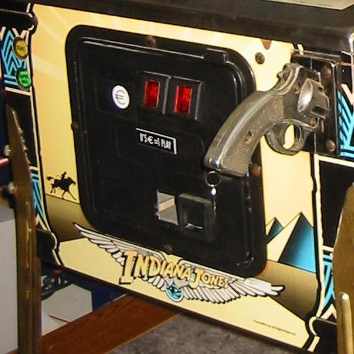
The front of the machine prior to the repaint. Only the blue is not faded,
all other color is gone.

Photo shot after the damage by the lockbar has been repaired, and the cabinet front repainted. With the naked eye, you can see some streaking
when you are close, but the photo does not show it.


Before and after pictures of the head.

Tight shot of Indy to show the texturing on his face. Incidently, the eyes were the
last thing I painted in. After I did that, the image seem to suddenly come alive.


Left side of the head painted.
See here for a full cab shot.
RGP comments
Clark Mills' repainting results with glass paint. Discussion.
See here for how I printed overlays to restore my Medieval Madness cabinet.
Pathway of Adventure Motor
Parts of the cabinet, including the front, were faded when I bought the machine. To remedy this, restorers often replace the cabinet decals. Due to personal reasons (cost, lack of expertise, machine off-line for weeks), I decided to follow an idea attributed to Rob "Sharpie Master" Bell. This approach uses Sharpie permanent markers to repaint the cabinet. The ink from these pens is translucent and impervious to water, making them a good candidate for this duty.
The front of the machine prior to the repaint. Only the blue is not faded,
all other color is gone.
These were Rob's tips
(reproduced
with permission):
- Take your time and keep your pen strokes even.
- Always have
your sharpie pointing downwards (for best ink flow).
- If you do not like the way a color looks or if you make a small error, keep wet q-tips close by to remove the ink before it dries.
- Use a ruler for long straight lines.
- Clean the entire area with alcohol first (test in a hidden area first). This will ensure the brightest colors.
- Use a fresh
set of pens and with chisel tips if available. This allows
wide
strokes to reduce the streaking.
- Use a ruler that can be flipped over such that the edge that touches the Sharpie does not touch the cabinet. This leaves no marks when you lift the ruler, and prevents the ink from wicking under the ruler.
- When you look closely, you will see streaks. This streaking is less with lighter colors. Minimize their appearance by stopping a stroke only at the edge, and then making one pass along the edge.
- Put down the lightest color first. This is because if you overlap, the pen will pick up the older color, and could contaminate the pen. This has less of an impact if you use the lightest color first.
- Alcohol will
completely remove Sharpie ink, even when dry. So if you do
not
like the result, it can be washed off in the future.
Photo shot after the damage by the lockbar has been repaired, and the cabinet front repainted. With the naked eye, you can see some streaking
when you are close, but the photo does not show it.
I removed the coin door
(put it
inside the cab, and did not demate the connector) and the lock down
bar. The legs were not removed. In the original
artwork,
the orange has a gradient, but I found that impossible to reproduce
with pens. I used the following colors: Yellow, Orange,
Black,
Red, and Light Blue. All were available in
chisel
tip except the yellow. Judging by the flow of ink,
I do
not think I used up much of any of the pens.
The cab of the machine was ok, but the head was also faded. I decided to repaint that also, but realized that Indy's face represented a special challenge. It would not look good to have his face color be solid. To give him a three dimensional look, I needed to figure out how to apply a gradient.
The cab of the machine was ok, but the head was also faded. I decided to repaint that also, but realized that Indy's face represented a special challenge. It would not look good to have his face color be solid. To give him a three dimensional look, I needed to figure out how to apply a gradient.
Before and after pictures of the head.
I used "Burgundy"
for
the leather whip, jacket and the hat. This gave the leather a
rich red color. If you look closely, you may see a white
highlight along the top edge of the whip. I traced this edge
with
the marker with its felt tip in the "up" position. This put
down
a slightly lighter layer next to the white. I then finished
the
rest with the tip down, making it darker. This gave the whip
a
round look. You can see a little of that in the bottom right
corner of the picture below. I did the same to create
contrast
and highlights in
Indy's hat. It turned out quite nice actually.
I then used a "Marigold" (yellow-brown) Sharpie for Indy's face. Regarding the gradient, my work with Photoshop gave me an idea: I could use a cotton swab with alcohol to wipe the color off in a gradual fashion. My notes regarding this tricky process:
I then used a "Marigold" (yellow-brown) Sharpie for Indy's face. Regarding the gradient, my work with Photoshop gave me an idea: I could use a cotton swab with alcohol to wipe the color off in a gradual fashion. My notes regarding this tricky process:
- Color the
area with the
marker It is not important in this
case to put down an even coat.
- Take a
cotton swab, and
apply a SMALL amount of alcohol to
it.
- Start
dabbing in the areas
that need to be light. Due to
the alcohol, the swab will absorb a lot of ink. The light
areas
should be the nose, cheek area, and the open chest area. If
you
use too much alcohol on the swab, it may ooze out and run down the
cab, or leave a big white spot.
- Work outwards in circular motions to the darker area. As the swab gets more saturated, it will pickup less ink. Keep the area under Indy's brim and under the jacket as dark as possible. If needed, add ink by using the Sharpie.
- In small
areas, use a Q-tip,
but preload it with ink, or it will draw a lot off the
cabinet.
Note the highlights on Indy's ears below.
- If you don't like the way it looks, alcohol will completely clean the ink off, allowing you another try. Once it is all clean, go back to #1 above.
- As
the swab is drying,
and just a little moist, wipe the entire
area again (with the ink laden swab) to smooth out any dab marks.
Tight shot of Indy to show the texturing on his face. Incidently, the eyes were the
last thing I painted in. After I did that, the image seem to suddenly come alive.
Left side of the head painted.
See here for a full cab shot.
RGP comments
Clark Mills' repainting results with glass paint. Discussion.
See here for how I printed overlays to restore my Medieval Madness cabinet.
Pathway of Adventure Motor
The mini playfield at
the top right
is powered by a small electric motor that tilts it
left-right.
When I picked up the machine, this motor was not running, but Randy
instructed me how to replace it. I purchased an equivalent
motor
from Radio Shack (part number 273-255 for about $3), and used that to
replace the broken motor. That part has now been since
discontinued, and 273-256 may also work.

Replacing the POA motor with a unit from Radio Shack. A thin wire is used
to wedge the original gear onto the new motor shaft. After this picture was
taken, the gear was pushed onto the shaft, and the excess was snipped off.
Replacing the POA motor with a unit from Radio Shack. A thin wire is used
to wedge the original gear onto the new motor shaft. After this picture was
taken, the gear was pushed onto the shaft, and the excess was snipped off.
The drive shaft of the
motor is
slightly narrower than the inner diameter of the gear. Others
have used spacers such as double
sided
tape to fill the gap, but I
decided to use a thin wire instead. The wire is 30 AWG
wire-wrap
wire that has the insulation stripped. It is just thick
enough to
slide on and off with force, but does not allow the gear to
slip.
After bolting the motor onto the gearbox assembly, I had to swap the
wires as the output shaft ran backwards. After the swap, it
worked perfectly.
Adding the "Lost Plastic"
The prototype series of the IJ machine have a plastic along the back wall to decorate the very rear of the playfield. This plastic was omitted from the production run of the machines. Owners that wish to decorate their machines will often add it back in by purchasing a reproduction. One example was offered on sale on ebay for $50 (+$20 shipping) in January 2006. This was a bit too steep for me, so I decided to look into making my own.
The scan is available in large format on ballsofsteel.net. It is separated in two halves, the right and left. I downloaded the images and with some measurements of the mounting holes for the rope bridge figured that its resolution is about 390 dots per inch. I took the files to the local "Staples", and had the scans printed on a color laser printer using high quality glossy photo paper. The cost was $7.60, much more reasonable than the reproduction. The result looked extremely nice and were very good color matches to the playfield. If the person at the print desk does not know how to accomodate a specific dpi setting, ask them to print the artwork so that each half is 12 inches wide.
Polarity information:
Wire the
existing connector to the motor such that a positive
voltage onto pin 1 of the connector on the A-15946 circuit board causes the motor
to turn clockwise (test with a benchtop supply).
voltage onto pin 1 of the connector on the A-15946 circuit board causes the motor
to turn clockwise (test with a benchtop supply).
Specifications of the
Radio Shack
motor are: body is 1 1/4" long,
1 1/16" wide. Shaft is 3/32" diameter.
The mounting plate seen above has a 3/8" center hole,
and two holes at 5/8" separation for the bolts
that attach the mounting plate to the motor.
Repair note for the PoA gearbox by Cliffy
1 1/16" wide. Shaft is 3/32" diameter.
The mounting plate seen above has a 3/8" center hole,
and two holes at 5/8" separation for the bolts
that attach the mounting plate to the motor.
Repair note for the PoA gearbox by Cliffy
Adding the "Lost Plastic"
The prototype series of the IJ machine have a plastic along the back wall to decorate the very rear of the playfield. This plastic was omitted from the production run of the machines. Owners that wish to decorate their machines will often add it back in by purchasing a reproduction. One example was offered on sale on ebay for $50 (+$20 shipping) in January 2006. This was a bit too steep for me, so I decided to look into making my own.
The scan is available in large format on ballsofsteel.net. It is separated in two halves, the right and left. I downloaded the images and with some measurements of the mounting holes for the rope bridge figured that its resolution is about 390 dots per inch. I took the files to the local "Staples", and had the scans printed on a color laser printer using high quality glossy photo paper. The cost was $7.60, much more reasonable than the reproduction. The result looked extremely nice and were very good color matches to the playfield. If the person at the print desk does not know how to accomodate a specific dpi setting, ask them to print the artwork so that each half is 12 inches wide.

The scanned plastic printed by a color laser printer on glossy photo paper.
It looks very authentic to the naked eye.
The two halves were
joined using the
glue from a glue stick. This is very suitable because the
glue is
dry, and prevents the paper from rippling due to absorption
of moisture. It also allows you a few minutes of working time
before it dries hard. I then cut the pieces out and installed
it
onto the back wall of the playfield.


The plastic uninstalled (top) and installed (bottom). It really dresses up the back area.
It is nearly impossible to find the dividing line between
the right and left halves of the artwork.

Another shot of the upper playfield. The right ramp and captive ball cage
have not been installed yet.
The white glossy paper
is probably
transparent enough to be backlit, but I do not wish to drill or cut the
back wall. See the next section for the lighting kit that was
added.
Lighting the Lost Plastic
I purchased some high-power white LEDs to light up the Lost Plastic that was created in the section above. They are 5,000 mcd and 15,000 mcd (millicandela) units from Marlin P. Jones. The normal operating current is 20mA, and they have a forward voltage of about 3-4 Volts. They cost $0.59 and $1.25 each respectively.

Modified LED lens (top) to result in a wider dispersion pattern.
This is the 5mm sized 5 candela unit.

Assembled light board. It has five modified LEDs of of 5 cd (candela)
brightness and one jumbo at a whopping 15 cd of light power.

The light board installed between the rope bridge plastic and the ramp.
The LEDs are aimed towards the Lost Plastic.

With the new light kit off, but with the top glass in place. Note the reflection
of the DMD obscures the Lost Plastic.
July 2006
update: I bought a Lost
Plastic from another RGP
member for
$35.
It will be installed at some point in the future.
It will be installed at some point in the future.
Lighting the Lost Plastic
I purchased some high-power white LEDs to light up the Lost Plastic that was created in the section above. They are 5,000 mcd and 15,000 mcd (millicandela) units from Marlin P. Jones. The normal operating current is 20mA, and they have a forward voltage of about 3-4 Volts. They cost $0.59 and $1.25 each respectively.
Modified LED lens (top) to result in a wider dispersion pattern.
This is the 5mm sized 5 candela unit.
A standard LED produces
a very
focused beam. Since I wanted to be able to mount the LED on the rope
bridge ramp, I needed a very diffuse pattern. I accomplished
this
by modifying the lenses of the LEDs. As shown above, I first
filed the round dome of the LED flat, and then drilled a dimple into it
with a very large drill bit. The concave lens resulted in a
wide
diffuse pattern.
Assembled light board. It has five modified LEDs of of 5 cd (candela)
brightness and one jumbo at a whopping 15 cd of light power.
Six LEDs were mounted on
a 3/4" wide
strip of perf board. This is the same width as the rope
bridge
ramp's metal side. They were soldered pair-wise
"back-to-back"
(anode to cathode) so that I could run off the GI circuit (which is AC
power). Then the three pairs are soldered in parallel to
minimize
the number of wires to the circuit board to two. In a
separate
experiment, I tried putting two LEDs in series, but the resulting
current was too low to produce the full optical power. I
wired
the lamps to the GI bulb at the "INDY" dividers in series with a 22 Ohm
resistor. This resulted in a total current of 67mA, which is
a
little over 11mA per LED (recall that each LED is on only one half of
the time). This curent level leaves some room for me to
brighten
the lights even more in the future.
The light board installed between the rope bridge plastic and the ramp.
The LEDs are aimed towards the Lost Plastic.
Before installation, I
insulated the
metal of the rope bridge ramp with some clear tape, and then attached
the mini-board onto the ramp's side with double sided sticky
tape. The plastic of the rope bridge hides the circuit board
and
LEDs from view. The thin white wire that leads to the circuit
board is passed through a hole in the back panel. During an
initial test, I concluded that the white LED's light was too white and
blue. I then applied a thin layer of watered-down yellow
acrylic
paint to take the edge of the blue color. It resulted in a
good
match with the rest of the playfield. Although using yellow
LEDs
is an option, I think that it would be too yellow, and I could not find
yellow LEDs with the same output power as white ones.
With the new light kit off, but with the top glass in place. Note the reflection
of the DMD obscures the Lost Plastic.
I noticed that the
various pictures
of the Lost Plastics light kits on the web do not show the final result
with the machine's top glass in place. The reflection from
the
DMD is bright enough to hide the Lost Plastic, and its lighting needs
to be strong enough to counteract that.

With the light kit on. The 15 cd jumbo LED is on the bottom to light up the scarab. Note that enough light gets under the ropebridge plastic to light it up completely. The side of the metal ramp does not cast a shadow onto it. For a picture of how it looked before I colored the white LEDs, click here.
The above picture shows
the view with
the LEDs on, and the top glass in place. As one can see, the
DMD's reflection tends to obscure the plastic, and it is understandable
why Williams chose to omit it from the production units.
Without
strong lighting, the plastic is hardly visible. The outer two
LEDs on the top and bottom are aimed sideways, and although not very
clear from the pictures, they do illuminate the left and right
halves. Since it was so inexpensive and easy to produce, I
may
build auxiliary light boards for the left and right sides in the future.
Since I only needed to buy the LEDs, and obtained the rest of the parts from my spare supplies, the cost of this mod was less than $5.
Since I only needed to buy the LEDs, and obtained the rest of the parts from my spare supplies, the cost of this mod was less than $5.
Repairing the idol lock
During the renovation, I removed all of the parts of the idol ruins except for the ball lock gate. As a result, it was sticking out above the playfield like a sore thumb. On one occasion, I passed my hand over the area, and snapped the gate clean off. I initially tried to epoxy the gate back to the stub that was left over on the armature, but the mechanical shock of the solenoid's actuation soon caused the glue to fail.

The idol lock gate was not removed and was damaged by my hand.
After some further thought, I decided to use a bolt to fasten the gate down. I made a new gate with some aluminum flashing (white), by cutting it out of a larger sheet with my tin snips. To dress up the plain white aluminum, I printed a target decal and glued it onto the gate.

The new gate made from aluminum flashing with a printed decal covering it.
I drilled a hole in the "foot" of the gate, and then drilled and tapped a hole in the remaining plastic on the armature. I then fastened the gate down with a screw. After installation, it looks much better than the original plain yellow gate. Even though I ordered four NOS gates from Marco Specialties ($4.50 each), I may not install them as I really like the look of the target at the exit of the idol lock.

The target decal really dresses up the idol lock door. The gate opens and closes properly.
During the renovation, I removed all of the parts of the idol ruins except for the ball lock gate. As a result, it was sticking out above the playfield like a sore thumb. On one occasion, I passed my hand over the area, and snapped the gate clean off. I initially tried to epoxy the gate back to the stub that was left over on the armature, but the mechanical shock of the solenoid's actuation soon caused the glue to fail.
The idol lock gate was not removed and was damaged by my hand.
After some further thought, I decided to use a bolt to fasten the gate down. I made a new gate with some aluminum flashing (white), by cutting it out of a larger sheet with my tin snips. To dress up the plain white aluminum, I printed a target decal and glued it onto the gate.
The new gate made from aluminum flashing with a printed decal covering it.
I drilled a hole in the "foot" of the gate, and then drilled and tapped a hole in the remaining plastic on the armature. I then fastened the gate down with a screw. After installation, it looks much better than the original plain yellow gate. Even though I ordered four NOS gates from Marco Specialties ($4.50 each), I may not install them as I really like the look of the target at the exit of the idol lock.
The target decal really dresses up the idol lock door. The gate opens and closes properly.
When I received the
machine, the
ramps were very corroded and discolored. One could almost
hear a
grinding noise when the ball rolled over them. Clearly
something
needed to be done to bring back the surface sheen.

State of the ramps at the start of the project. They were corroded and discolored. Note overall dust and dirt everywhere.

I also made a protector for the two plastics under the right (clear) ramp.
Both the 'U' shaped one and the one behind it (both shown) were broken at the
bolt holes due to ball hits from the pop bumpers and
the standup target.
I also made sling shot and the mode start saucer protector.
Target repair
After about a month of play, one of the plastic drop target tabs snapped. These get a lot of abuse, and can still be purchased. However, I decided to attempt a repair while I was waiting for the new ones to arrive.

Oops. The middle drop target with its head snapped off.

I used an end mill in my hand held Dremel attachment to rough up the middle channels.

The finished result. Although only the middle tab broke, I had mixed up enough
epoxy to allow the reinforcement of all the tabs.
State of the ramps at the start of the project. They were corroded and discolored. Note overall dust and dirt everywhere.
From inspection, I could
tell that
the original color of the ramps were brass. This struck me as
a
bit odd as I felt that the silver color of stainless matched the other
ramps better. Nevertheless, I purchased a brass home
electroplating kit
from
www.caswellplating.com.
After
carefully reading the instructions, I buffed the ramps clean with
1000 grit sandpaper to bring them to a silver shine, and proceeded to
electroplate them. However, my results were poor. I
was not
able to put down a thick layer of brass. I could tell some
brass
was being put down, but it was faint; even after many
attempts.
After consultation with the company, it turns out that to plate brass
onto stainless, I would first need to plate with a "Stainless Steel
Activator". Afterwards, I could plate with brass.
The fact
that this was not mentioned in the instructions is somewhat puzzling to
me.
After considering it, I decided to leave the ramps the unfinished bright silver color. I can always plate them at a later date, but I like the fact that I can bring them back to a shine by buffing them, and that this way they match the color of the other metal ramps.
Sept 2008 update: Wade Lanham informs me that the ramps are not stainless, but chromed mild steel.

The finished ramps in their native bright silver finish.
After considering it, I decided to leave the ramps the unfinished bright silver color. I can always plate them at a later date, but I like the fact that I can bring them back to a shine by buffing them, and that this way they match the color of the other metal ramps.
Sept 2008 update: Wade Lanham informs me that the ramps are not stainless, but chromed mild steel.
The finished ramps in their native bright silver finish.
Now when a ball rolls
along the ramps,
there is no sound, and the bright finish adds a touch of shine to the
playfield.
Spinning prop mod
Many IJ owners install a mod that spins the propeller on the bi-plane. A kit is available for a reasonable $30, but I decided to build my own.

From my son's toy box, I found a very small motor and a propeller.
Note that the motor is smaller than the head of a pencil!

The painted prop and motor mounted to a copper wire. I later
added more color accents to the prop (see below).

The prop mod installed into the bi-plane. Note the jog in the copper wire to allow me to
access the nut with my socket driver.

Unretouched photo of the spinning propeller on my workbench. Vroom!
Once the motor and biplane were assembled together, I proceeded to install the assembly into the machine's playfield. Although it fit, I could tell clearances were small due to the large size of the propeller. To improve reliability, I decided to trim 1/4" of each of the prop's blades. I also used this opportunity to paint the tips bright yellow, and added black bolt accents to the base of each prop blade.
The motor of the biplane was wired in series with a 10 Ohm 1/2 Watt resistor to the left ramp entrance arrow. This causes it to spin occasionally during attract mode, and often during game play.

The finished assembly in the machine. Note the added color
touches (yellow tips and black bolt accents).
Ball trough mod
A common problem with this machine are the two opto-electronic circuit boards on the ball trough. These are mounted solidly on a platform that also contains a strong solenoid. The vibration and shock from this solenoid causes the opto circuits to wear out faster than expected. A common mod is to shock mount the boards by using grommets. The grommets were part number 731K-ND from Digikey.

Rubber grommet inserted into the mounting hole (right), and unmodified hole (left).
After a fit check, I realized that I had to cut the bottom right corner off the
board so that it would not touch the trough. The following night after
this image was shot, I cleaned the excess flux from the LED joints.
I enlarged the hole with a 1/4" drill bit (no traces are nearby). However, the grommets were a bit big, and I had some effort pushing them into the hole. After they were mounted (two), I located the board into the ball trough and found out that the extra thickness of the grommets caused the board to touch the metal of the trough on the outer edge of the playfield (rightmost in the picture below). With my circuit board nibbler and a file, I cut the circuit board back. Fortunately, the board is of simple double sided construction, and there are no traces in the overlapping area.

Circuit board mounted into the trough. Note the slight clearance near the blue
line. I had to cut the circuit board back to fit.
Jackpot plastic protector
This plastic, being in the center of the playfield, gets a lot of ball strikes, and is frequently broken. I purchased a new one from Marcos for $16. When I received it, I was disapointed to see that its color was not the bright orange of the existing part, but looked brown. Seeing the color mismatch, I decided to make my own repro and return the plastic. I called Marcos, and the conversation with Lisa went something like this:

The old (left) and the new plastic (right). The old looked worse when I first got the machine, but I touched up the missing orange with acrylics.

The protector was cut from a flexible clear sheet of Lexan. This is the view
from the underside.

Hard to see, but there is a plastic under the left and right portions of this plastic.
With this improvement, it should prevent damage for a long time. This
picture shot before the ramps and the airplane
were installed.
Many IJ owners install a mod that spins the propeller on the bi-plane. A kit is available for a reasonable $30, but I decided to build my own.
From my son's toy box, I found a very small motor and a propeller.
Note that the motor is smaller than the head of a pencil!
I found a propeller and
motor from my
son's toy box. The prop was prepared by light sanding and
then
painting
with white Fusion
paint. The spinner was painted with red acrylic.
The motor
was from a ZipZap
electric
car (available at Radio Shack). It was mounted to a
thick
copper wire using solder. The
flexible copper wire allows me to precisely position the motor in the
engine compartment. From examining the pictures of this
kit,
it seems to me that the same motor is used in it.

The tiny motor was from a "ZipZap" car. This is an excerpt of the original
manual so that the reader has an idea where to find them.
The tiny motor was from a "ZipZap" car. This is an excerpt of the original
manual so that the reader has an idea where to find them.
The painted prop and motor mounted to a copper wire. I later
added more color accents to the prop (see below).
I soldered the motor to
the 12AWG
copper wire by wrapping a few turns of wire-wrap wire around the
assembly. This allowed me to securely solder the two together
with the minimum of heat to the motor. I was afraid that
excessive heat would affect the permanent magnet inside the
motor. The copper wire was then bent into the optimal shape
to
allow access to the nut that fastens the bi-plane together, and to
position the motor as far forward as possible.
The prop mod installed into the bi-plane. Note the jog in the copper wire to allow me to
access the nut with my socket driver.
Unretouched photo of the spinning propeller on my workbench. Vroom!
Once the motor and biplane were assembled together, I proceeded to install the assembly into the machine's playfield. Although it fit, I could tell clearances were small due to the large size of the propeller. To improve reliability, I decided to trim 1/4" of each of the prop's blades. I also used this opportunity to paint the tips bright yellow, and added black bolt accents to the base of each prop blade.
The motor of the biplane was wired in series with a 10 Ohm 1/2 Watt resistor to the left ramp entrance arrow. This causes it to spin occasionally during attract mode, and often during game play.
The finished assembly in the machine. Note the added color
touches (yellow tips and black bolt accents).
Ball trough mod
A common problem with this machine are the two opto-electronic circuit boards on the ball trough. These are mounted solidly on a platform that also contains a strong solenoid. The vibration and shock from this solenoid causes the opto circuits to wear out faster than expected. A common mod is to shock mount the boards by using grommets. The grommets were part number 731K-ND from Digikey.
Rubber grommet inserted into the mounting hole (right), and unmodified hole (left).
After a fit check, I realized that I had to cut the bottom right corner off the
board so that it would not touch the trough. The following night after
this image was shot, I cleaned the excess flux from the LED joints.
I enlarged the hole with a 1/4" drill bit (no traces are nearby). However, the grommets were a bit big, and I had some effort pushing them into the hole. After they were mounted (two), I located the board into the ball trough and found out that the extra thickness of the grommets caused the board to touch the metal of the trough on the outer edge of the playfield (rightmost in the picture below). With my circuit board nibbler and a file, I cut the circuit board back. Fortunately, the board is of simple double sided construction, and there are no traces in the overlapping area.
Circuit board mounted into the trough. Note the slight clearance near the blue
line. I had to cut the circuit board back to fit.
Jackpot plastic protector
This plastic, being in the center of the playfield, gets a lot of ball strikes, and is frequently broken. I purchased a new one from Marcos for $16. When I received it, I was disapointed to see that its color was not the bright orange of the existing part, but looked brown. Seeing the color mismatch, I decided to make my own repro and return the plastic. I called Marcos, and the conversation with Lisa went something like this:
- Me: I would like to return this plastic because the color
does
not match the original.
- Lisa: Did you check the color under the protective plastic?
- Me: Uhh, what protective plastic?
- Lisa: Hang on, I will pull one of these parts, and check about the plastic. (after a pause). Yes, the color is bright orange underneath.
- Me: Thank you. I did not realize there was a protective plastic.
The old (left) and the new plastic (right). The old looked worse when I first got the machine, but I touched up the missing orange with acrylics.
The original plastic was
damaged in
two ways: 1) cracks on the edges facing the flippers due to ball
strikes, and 2) missing paint from frequent banging against the metal
ball guides underneath. Both of these can be mitigated by a
clear
protector, which I made by cutting them out of a sheet of clear
plastic. This plastic is tough but slightly flexible, but can
be
easily shaped by tin snips. A set of protectors is also
available
from Marcos for $45.
The protector was cut from a flexible clear sheet of Lexan. This is the view
from the underside.
After cutting, I used a
small file to
smooth the edge. This made the white edge (due to cutting)
disappear and become almost invisible as can be seen below.
The
thickness of the protector also prevents the Jackpot plastic from
resting and rubbing on the metal ball guides.
Hard to see, but there is a plastic under the left and right portions of this plastic.
With this improvement, it should prevent damage for a long time. This
picture shot before the ramps and the airplane
were installed.
I also made a protector for the two plastics under the right (clear) ramp.
Both the 'U' shaped one and the one behind it (both shown) were broken at the
bolt holes due to ball hits from the pop bumpers and
the standup target.
I also made sling shot and the mode start saucer protector.
Target repair
After about a month of play, one of the plastic drop target tabs snapped. These get a lot of abuse, and can still be purchased. However, I decided to attempt a repair while I was waiting for the new ones to arrive.
Oops. The middle drop target with its head snapped off.
I used an end mill in my hand held Dremel attachment to rough up the middle channels.
I first needed to rough
up the
plastic to allow the epoxy more surface area to bite into.
This
was accomplished by my end mill and my handheld drill. This
light
tool allows fine control, and I quickly had the two middle channels
thoroughly roughed up. I then dusted and degreased the area
with
Q-tips and isopropyl alcohol. For the main structure, I
decided
to use lightweight aluminum strips cut from a piece of flashing.

Small strips of aluminum were cut from a piece of flashing with a pair of tin snips.
They are then sanded rough with 60 grit paper.
Small strips of aluminum were cut from a piece of flashing with a pair of tin snips.
They are then sanded rough with 60 grit paper.
The finished result. Although only the middle tab broke, I had mixed up enough
epoxy to allow the reinforcement of all the tabs.
Epoxy was deposited in
the crack
itself, and then the head was replaced onto the tab. After
slathering epoxy into the channel, one of the aluminum strips was
pressed into the bed of glue. This resulted in a very strong
joint with lots of surface area. Since the repair of the
middle
one went so smoothly, I decided to reinforce the two side ones as well.
Update: After a few
days.....the
middle target broke again. This shows that
even with surface prep the epoxy will still fail due to the ball strikes.
Oh well, time for new ones.
even with surface prep the epoxy will still fail due to the ball strikes.
Oh well, time for new ones.
New targets
I obtained new targets from another RGP member at low cost, and needed new decals for them. Instead of buying them (they periodically come up on ebay for ~$12), I decided to print them myself.

Left: decal from ballsofsteel.net. Right: modified version
for brighter colors.

Left: printed image from ballsofsteel.net. Middle: Original target. Right: printed from modified image.
The rightmost image looks more like the original except it has darker blacks.
I obtained new targets from another RGP member at low cost, and needed new decals for them. Instead of buying them (they periodically come up on ebay for ~$12), I decided to print them myself.
Left: decal from ballsofsteel.net. Right: modified version
for brighter colors.
My initial printing with
a color
laser printer on glossy paper was not very satisfactory.
Compared
to the existing target, the yellow color at the top was not very
bright, and the orange was also a bit dark. With image
manipulation software, I increased the saturation of the colors, and
printed a second batch. This time, it looked very close to
the
orginal, and I was satisfied.
Left: printed image from ballsofsteel.net. Middle: Original target. Right: printed from modified image.
The rightmost image looks more like the original except it has darker blacks.
The printed images were
cut out with
a very sharp pair of scissors, and glued to the target with glue from a
glue stick. This type of glue is dry, and does not cause the paper to
curl. I then laminated the target with clear tape, and the
result
look very close to the original (except for the part under the
playfield).
11/2010 update: Links from theteardown.com:
Mode Start Saucer Mods
Two mods were made to the mode start saucer: one was the application of foam rubber on the deflector bracket, and the second is the addition of LED lighting on the saucer (ball trap).

Two mods on the Mode Start Saucer. A rubber pad (black square) prevents
bounce outs, and the saucer is lit up by an LED. The view is better
from the point of view of the player, and not very obvious from this low angle.

The new amp is powered from the 12V available at the coin
door interface board.


Before and after pictures of the flippers. They are courtesy of another RGP member.
11/2010 update: Links from theteardown.com:
- Very detailed redrawing of the target artwork.
- General article on making
decals and stickers.
Mode Start Saucer Mods
Two mods were made to the mode start saucer: one was the application of foam rubber on the deflector bracket, and the second is the addition of LED lighting on the saucer (ball trap).
Two mods on the Mode Start Saucer. A rubber pad (black square) prevents
bounce outs, and the saucer is lit up by an LED. The view is better
from the point of view of the player, and not very obvious from this low angle.
One common problem with
the mode
start saucer is that balls may bounce out when they are hit into the
saucer. To prevent this, one can purchase a rubber padded
deflector from places like Pinball
Heaven. A simpler way is to apply some adhesive
foam rubber
on the metal tab of the deflector. To make the application
easier, use a piece of double stick scotch tape to stick the rubber pad
onto your finger. Then, reach into the mechanism and stick
the
pad with its own adhesive onto the deflector. I obtained the
rubber padding from Martin (pinbits.com).
It
is the same material that was used on my MM
Merlin ball lock. I could tell this rubber pad
would be
effective as soon as I shot my first ball into the saucer.
The
ball no longer makes a sound when shot into the lock, and just goes
'dead'.
Update on the rubber pad (10/23/06): It is about 1/8" thick and has an adhesive back. I performed a drop test over a concrete floor, and dropped a pinball from one foot height. The ball bounced about 1/8" to 1/4". Note that the pad was not glued to the concrete floor, and some bounce is due to the remaining curvature in the pad. I presume it would be more 'dead' if glued down.
The second mod is to light up the normally dark saucer with a jumbo super-bright white LED that was painted red. This was then wired to the GI circuit with a current limiting resistor. As can be seen from the photo above, this mod causes the saucer to light up like a pit of fire, and is very aestheticaly pleasing. Although the low angle of the photo makes it not very obvious, the saucer is quite bright from the point of view of the player.
Adding bass boost
On my TOTAN and MM, the sound was greatly improved by changing the speaker and increasing the gain on the cabinet speaker amplifier. However, this did not work at all on the IJ. The sound did not sound right. There was too much midrange, and after boosting the gain of the cabinet speaker up very much, the amp started to clip. Clearly, the WPC-DCS generation of electronics has inadequate amplifiers for big sound, and I realized that I needed to add a amplifier such as others have done. Martin Reynolds recommended the Rampage AXT120 from Audiovox, and since it was only $15 (+$10), I decided to give it a try.

The new amp mounted next to the new cabinet speaker.

Wiring diagram of the amplifier. The "high level inputs" are used. A passive low-pass
filter was added to reduce the midrange. The gain of the AudioVox amplifier
is turned up to maximum.
Update on the rubber pad (10/23/06): It is about 1/8" thick and has an adhesive back. I performed a drop test over a concrete floor, and dropped a pinball from one foot height. The ball bounced about 1/8" to 1/4". Note that the pad was not glued to the concrete floor, and some bounce is due to the remaining curvature in the pad. I presume it would be more 'dead' if glued down.
The second mod is to light up the normally dark saucer with a jumbo super-bright white LED that was painted red. This was then wired to the GI circuit with a current limiting resistor. As can be seen from the photo above, this mod causes the saucer to light up like a pit of fire, and is very aestheticaly pleasing. Although the low angle of the photo makes it not very obvious, the saucer is quite bright from the point of view of the player.
Adding bass boost
On my TOTAN and MM, the sound was greatly improved by changing the speaker and increasing the gain on the cabinet speaker amplifier. However, this did not work at all on the IJ. The sound did not sound right. There was too much midrange, and after boosting the gain of the cabinet speaker up very much, the amp started to clip. Clearly, the WPC-DCS generation of electronics has inadequate amplifiers for big sound, and I realized that I needed to add a amplifier such as others have done. Martin Reynolds recommended the Rampage AXT120 from Audiovox, and since it was only $15 (+$10), I decided to give it a try.
The new amp mounted next to the new cabinet speaker.
The amplifier is powered
from the 12V
that is available at the coin door interface board. After
connection, I found that the midrange was too loud, just as before
(except no more clipping). To address that, I added a passive
low
pass RC filter with a corner frequency of about 240
Hz.
This
was selected by experimenting with various values until the predominant
sound came from the backbox speakers, and only a nondirectional rumble
could be felt by the player. To compensate for the reduction
in
amplitude (the input impedance of the "high level input" is 100 Ohms),
I increased the gain of the backbox amp by putting a 110 Ohm resistor
across R37. The RC filter was implemented on a small perf
board
and mounted next to the amplifier.
Wiring diagram of the amplifier. The "high level inputs" are used. A passive low-pass
filter was added to reduce the midrange. The gain of the AudioVox amplifier
is turned up to maximum.
During the initial
hookup, I did not
connect the chasis input connection and there was a loud hum on the
speaker. This hum would only go away when both connections to
the
WPC-DCS amplifier were disconnected. It thus looked like a
ground
loop/common-mode voltage problem. After connecting the
chassis
connection. to the ground braid of the cabinet, the noise went away.
The new amp is powered from the 12V available at the coin
door interface board.
Using an ammeter, the DC
power supply
current into the amp was measured to be a steady state of 200mA,
peaking at 500mA during loud passages. I don't think this
additional load will overstress the power supply. Since it is
unregulated and fused, it should be easy to repair if any problems
occur.
New flipper and rubber
colors
Due to frequent play, the tip of the left flipper broke. I received a free one from Rome, an RGP member. He also included two yellow flipper rubbers! I think they look most appropriate on the IJ.
Due to frequent play, the tip of the left flipper broke. I received a free one from Rome, an RGP member. He also included two yellow flipper rubbers! I think they look most appropriate on the IJ.
Before and after pictures of the flippers. They are courtesy of another RGP member.
Page 1 of Indiana Jones Machine
(c) 2006 Edward Cheung, all rights reserved.