| Home | Job | Pinball | Photo Album | Automotive | Press/Awards | Contact |

HP 1652B Scope/Logic Analyzer
Power Supply Repair

My HP1652B logic analyzer in use
I had been using my HP 1652B scope/logic analyzer for many years, and it was with sadness one day in 2015 that I found out it would not power up and had a problem. I could hear a soft ticking sound and smelled a burning smell. I did some searching and found only this account of someone repairing theirs. In that case, it appears the capacitors had gone bad. I hoped mine would be the same issue and started the repair.
With the benefit of hindsight, the best way to access the power supply module is as follows:
- Remove the top cover by using a T10 hex driver.
- Remove the disk drive (A6 below) by unscrewing it (H5) and pulling it out the front.
- The power supply module is held by two plastic pins near the front and back (MP11). Pull those out.
- Disconnect the cables to the power module (one input and one out).
- Slide module (a5) out to the (right) side.
- Remove top screws and the top lid on the module's case.
- Unscrew board and remove from case.


Photo of the component side of
the board.
Starting with the red connector in the top left and going roughly clockwise, this is the function of the parts as far as I can tell (note 'left'/'right'/'top' etc refer to the orientation in the above image):
- The red connector is the input power. There are two pins for the back panel switch and two for input power.
- The 5Amp input fuse is below it.
- The two grey blocks and the yellow transformer is the input EMI filter.
- The small black block below the bottom grey is the full wave bridge on the input power.
- The two large caps in the bottom right are to hold the +V and -V main DC power. When the scope is disconnected from the power supply, these read + and - 166V. With the scope plugged in, it will be about 165V. To measure this, use the 'top' lead of R1 (between the two black capacitors) as the return. The bottom lead of R1 is -V. R2 (visible here) is above the right most cap, and its left lead is the +V terminal.
- The big transistor (TIPL755) with the heat sink in the middle is the main chopper of the DC bus.
- The large transformer in the middle with the CAUTION sticker is the main transformer that is pulsed by the above transistor. It is the output windings of this transformer that provide the five output supplies: 5V, 3.5V, -5V, 12V, and -12V.
- I suspect the transformer below the main one couples energy back to the primary side to modulate the main transistor's duty cycle to regulate the output voltage.
- The board on the bottom is the main controller. The five pots allow you to trim the voltages. I say that because these five pots are accessible through a slot machined into the top cover.
- Above the small board on the left are all the filters for the secondary side. You will see several metal 'fins' sticking out of the board, and diodes soldered to them. These are the rectified and filtered output buses. So you can monitor the unregulated buses by tapping into these. Typical voltages are from 3 to 16V, so nothing particularly dangerous. The rectification is a single diode, so half-wave.
- The chokes/coils with the red dots connect the quad capacitor bank to the output section.
- The five TO-220 packages along the perimeter heat sink are the linear regulators for the five outputs.
I first decided to try and isolate the fault by disconnecting most of the power diodes from their output heat sinks. With this process I was able to isolate the problem/short to the bus that is near the bank of 8 identical filter capacitors. These are 1000uF electrolytics. The vertical 'fin' near the transformer appears to be one of its output terminals, and four diodes bridge from this fin to two horizontal ones adjacent to the octal cap bank. I removed the bottom four caps in this octal bank and saw quickly that there was a short between the case of C8 and a trace below. There was a prominent burn mark on the trace. See below for an image.
The damage/short area on the board is right by C8.

I tested all four of the capacitors from C7 through C10, and found they all had a good value (about 1100uF). Their ESR all tested to be ~0.05 ohms, and their insulation resistance was in the MegOhm range. As a result, I judged them all undamaged and installed them back into the board.
On power up, the unloaded power supply board still produced a soft ticking noise, but no burning smell. I reasoned that the Switched Mode Power Supply may need a minimum load, and was perhaps shutting down due to lack of load. The voltages I measured on the output connector was as follows. Top reading is on the left most terminal:
- 4.8
- 4.8
- 4.8
- 4.8
- Return / ground
- Return
- Return
- Return
- 3.5V
- Return
- -5
- Return
- 12V
- Return
- -12V
- Return
- 10.7V
- -5.2V
- 11.2V
- Return
I then powered down and plugged in the scope. On subsequent power up, success! The fan spun up and the passed self-test. I then reinstalled the disk drive and the cover and the test after that the system worked normally.
Transferring Data
The analyzer has a 25-pin female RS-232 port in the back, and I decided to see if I could transfer data gathered by the analyzer for further processing on a PC. With some experimentation I found out that I could capture the data, as many as 1024 samples with a single pod. Adapter cable information is below.
Male 25 pin D (LA) Female 9 pin D (PC) Function
2 2 * Data to PC >
3 3 * Data to LA <
4
7
RTS >
5
8
CTS <
6
6
DSR <
7 5 * Return Ref
8
1
DCD <
20 4
DTR >
Adapter to connect the serial output to a PC.
">" are data to PC, "*" are for minimal interface.
(Ref: page 3-3 of programming manual).
My notes on setting this up (on Logic Analyzer):
- I/O -> I/O Port Configuration.
- Use 9600,8,N,1 speed
- In "Printer Information", Select "Alternate"
- Setup LA for "State" and "State Listing" display.
- I/O -> Print All. Then "Select"
- You can hit "Stop" to Halt
Example capture stream with Hyperterm:
PIA - STATE LISTING
Label > R/_W RS DATABS SPARE CS
Base > Symbol Bin Hex Bin Hex
+0000 READ 01 00 1 5
+0001 WRITE 01 00 1 5
+0002 WRITE 00 7F 1 5
+0003 WRITE 01 34 0 5
+0004 READ 00 00 0 5
+0005 WRITE 00 00 0 5
+0006 READ 11 00 0 5
+0007 WRITE 11 00 0 5
+0008 WRITE 10 FF 0 5
+0009 WRITE 11 34 0 5
+0010 READ 10 00 0 5
+0011 WRITE 10 00 0 5
The above is a capture of the pins on a PIA on a System 9 board upon startup.
Floppy Drive Emulation
Being mechanical, the floppy drive has always been a concern for me. In July 2024, I started having problems with reading a few of the disks that have always worked fine. The original floppy is the Sony 3.5" MP-F52W-30 that spins at 600 rpm and is Double Density (DD). I found out that there are a few floppy drive emulators and the one most often used and available for a low price on Amazon was the Gotek SFR1M44-U100.
One objective I had was to figure out a way to have _both_ the floppy and the Gotek connected, and switch manually from one to the other. In this manner, I could copy over all the configuration and setup files that I had on my floppies. Fortunately, these drives come with enable lines (called Drive Select in the manual), and my intent was to use these and a manual toggle switch to go from one to the other.
I worked on my own at first and tried the factory firmware that comes on the Gotek. That did not succeed and the Analyzer did not recognize the drive. It would beep after power up with a Disk Error. In my research I found that there are some firmware alternatives such as "HxC" that are developed by private individuals. And although there were no details, someone had interfaced an HxC to a 1652B in the past.
HxC has a powerful firmware customizer that allows you to put in all kinds of options to modify the drive behavior, which is useful as the Sony drive is not exactly the common PC format. Despite my best efforts, the closest I got was to be able to boot off the floppy, switch to the Gotek, and format the Gotek. But copying files to it still did not work. In desperation, I reached out on the HxC user forum, and Jeff the administrator was able to help me solve the problem. The exchange is documented in this thread. In the end, the problem was found to be specific to the MCU chip on my Gotek (QFN32 version of the AT32F415). Jeff had to move the Disk Change line to an unused pin, and I was finally able to use the Gotek to boot from and store my user files.
To replicate this setup, you will need to modify three areas: 1) Ribbon Cable, 2) Gotek, and 3) the USB stick.
1. Preparing the ribbon cable
Per page 12 of the datasheet (link below), we can see that the power feed is integrated onto the 34-pin drive connector. The first thing I had to do was modify the ribbon cable to interrupt and intercept the power. I did this by purchasing a 34-pin male-female extender, and then pressed on a new 34-pin IDC female connector into the middle of it, which will be the tap for the Gotek.
The "Y" cable made from a male-female 34-pin extender.
The following mods were performed:
The technique I used was to gently use a razor to part two conductors and then observe closely how they separate to make sure you don't cut into the insulator. The above interrupts 12 of the 17 conductors of one row. It looks a bit messy but doing it this way is the best way I know of doing this many splices.
- 5V was interrupted and wired past the middle connector. Power was split off for the Gotek (red).
- 12V was interrupted and wired across to supply the floppy drive (yellow wire).
- Pin 1 (Disk Reset) was interrupted and wired across the Gotek. Since the Gotek grounds pin 1, it disrupted eject detection.
- The bypass line for Pin 1 is connected to Gotek Pin 4. On the board, this line goes to J8-JK terminal.
- Pin 10 (Drive Select 0) was interrupted and used to select between the two drives. Pin 10 of the desired drive is grounded by a toggle switch to select it. The Logic Analyzer does not actively toggle the Drive Selects and always has pin 10 low.
- Ground/Return (three lines) were tapped for the Gotek power connector (black).
- I also added a second female 34-pin IDC connector so I could monitor the signals with another Logic Analyzer (Monitor).
The Monitor connector above was very useful in allowing me access to figure out why the initial code loads were not working. I connected a second logic analyzer to this location to monitor the control signals.
Example waveforms showing signals on the ribbon cable. It provided Jeff from
HxC insight into what the interaction was with his code and the Analyzer.
More in the HxC forum thread.
Two drives connected to the Logic Analyzer.
In the image above, you can see the two drives plugged in.
2. Preparing the drive
I followed the instructions on the HxC site to program a bootloader onto the chip, and programmed custom firmware from the HxC site for the drive. This writes over the factory firmware. I then followed Jeff instructions and wired Pin 4 on the ribbon to an unused MCU input. This line does not exist in a normal PC disk drive but is used by the Analyzer to know when a new floppy has been inserted. The only other mod is to insert the S0 jumper to connect the above signal through. There is a file package in the links below with more details.
3. Preparing the USB stick
I formatted a USB stick with FAT32 and copied over the configuration file (.CFG) and the .HFE file that Jeff sent me to it. The bootable HFE file has the same revision of System file that I have (rev 2.11), but this also includes the "Inverse Assembler". I have not encountered this before and do not know what that is. But I was able to use this system image just fine after deleting the Assembler files. Each HFE file forms an image of a floppy, and you can have many in one USB stick. The images are selected by pushing the black buttons on the Gotek and the numerical display will show which images the Analyzer will see. This is super convenient compared to swapping out floppies. The HFE files can also be backed up on the PC. In my situation, disks 0 and 1 are boot images, disk 2 and 3 has my Logic Analyzer configuration files. Disk 4 boots the system up in scope mode, and Disk 5 has scope mode configuration files.
In use
The image below shows the finished single drive configuration after the development and the copying over of the configuration files. I also shot a video but of the dual drive configuration to show the disk switching in action.
HP1652B Logic Analyzer with Gotek drive and HxC firmware installed.
The result looks very clean.
YouTube video of the Gotek in a dual-drive setup
LIF File Tools
The individual scope configuration files on the floppy disks have the .LIF format. These are encapsulated in the .HFE file on the USB stick, each representing a floppy image. A user on the HXC forum was kind enough to develop some python code to parse the files and allow individual manipulation of the configurations using hxcfe.Then with this python program, you can to various manipulations on the LIF, such as directory listing, extracting or inserting one scope configuration, etc.
First, convert the .HFE into combined .LIF volume (Windows command line):
hxcfe -finput:filename.hfe -conv:RAW_LOADER -foutput:filename.lif
python lifutils.py dir filename.lif python lifutils.py rm filename.lif NAME_TO_DELETE python lifutils.py get filename.lif NAME_TO_FETCH python lifutils.py put filename.lif NAME_TO_UPLOAD python lifutils.py pack filename.lifFinally convert the .LIF back into an .HFE with this XML file so that the scope can read and use them. See here for the thread on this topic.
Software Capture of Screen Print
The other mechanical input/output of this old device is screen captures. It supports printing via serial (or HI-IB) to a Thinkjet printer. I decided to try and see if I could convert this stream to an image.
I first started with the capture of the serial stream and pulled the result up on my Neo Hex Viewer. From what I could see on page A-2 of the Thinkjet Owner's Manual, the graphics commands are preceded by 6 byte header consisting of "<ESC>*b74W" (hex 1b,2a,62,37,47,57). I could see these packets in the file, but the packet is a lot longer than expected and interspersed with additional random bytes. See below, with the benefit of hindsight, I know the first (top) line of the image is a line of black pixels. So the packet should only contain 0xff bytes. But there are many characters interspersed.
Hex view of one packet in the captured stream.
Looking at the viewer above, you can see the packet header in the top-left. After the 'W' is the start of the pixels (top row of image), and they should all be 0xff. Counting the number of good 0xff bytes, we have 74 (decimal). That matches the expected quantity in the packet header. Total length of the packet is 192 (decimal), or 118 extra bytes.
The first rendering of this stream produces the image below. You can see these columns of garbage data breaking up the image. What is interesting is that these are perfect columns. So they must be produced by the Logic Analyzer and not the PC or cable doing the capture. I initially only had a three wire interface (marked by * in the table above), and added the handshake lines. But that did not resolve the issue. I found that using "None" or "XON/XOFF" for flow control produced the same results.
Initial result of converted stream.
I decided to add a filter to the software that notes which byte locations in the first packet do not contain the 0xff, and since they are perfect columns, the same bytes in the next packet are also ignored. By doing this I could filter out the bad columns. The result is below. What is nice about this algorithm is that it can also handle a stream that is not corrupted.
Successful conversion to bitmap of stream. The image is 600x400.
Compare to a photo.
As for Logic Analyzer setup, I found that configuring for Thinkjet or Quietjet produced the same files. Using Laserjet would produce packets that are 87 bytes of payload (compare to 74 above). I did not parse them. Setting to "Alternate" produced a file without discernible headers, but I could see a similar corruption interspersed between the graphics data. Setting width to 13.5" or 8.5" did not affect the data file that I could see. I also found that printing faster than 2400 baud would cause data corruption. This unfortunately means each print takes over two minutes. An example of running at 19200 is shown here.
Incidentally, during the writing of the conversion program, I needed a bit of software to produce a bitmap file. I would have needed to find out the convention and figure out how to write out an pixel array to file, etc. Instead of that I decided to use ChatGPT to write this code block for me. I simply used the prompt "simple bitmap generator C code", and it produced code that worked immediately. Further use showed a small error in the ordering of the RGB bits in the code, but I was surprised how easy it was to do it this way.
Update. I decided to use my scope to look at the RS232 stream to try and explain the errors when transferring at high baud rates. To my surprise, I saw no issues with the waveform. The transitions were sharp and there was a big open eye. This made me wonder if the problem was related to the non-ASCII data being transferred. I decided to switch to a USB RS232 device and that actually made the problem worse. The stored files were much larger and many of the packet headers were now corrupted. I then used a Sena SS100 serial to Ethernet adapter. To my surprise, the captured files were much smaller (35Kbytes) and had no corruption. So in the end, it appears that my conclusions were incorrect and the high rate errors and bad columns were related to the receiver and not the Logic Analyzer. I did not modify my converter app as it handles the clean files just fine. Another data point is that I have in the past been able to transfer many kbytes of data when in State mode, but that is almost all ASCII type data. This screen print is binary in nature.
A zip file of the Bitmap converter can be downloaded with the following files:
- cap.bin - Raw captured stream from HP1652B (with column issue).
- print2bmp.cpp - source code
- print2bmp.exe - console app to convert above capture to bitmap
Low Cost Alternative
During the construction of the antenna compass project, I wanted to be able to have the SPI stream from the 3-axis magnetometer automatically decoded into bytes and whole messages. I found an inexpensive logic analyzer unit from Sparkfun for less than $30. The really powerful feature is serial stream decoding with the PulseView software package, and many protocols have been contributed by the community including SPI and UART. I suspect this unit is a clone of a Saleae product as the PulseView configuration has that name.
This unit features an 8-channel input and it comes with a ribbon pin header. I arranged the 8 inputs in the same order as half of the HP header so that the two can be interchanged.
 Low cost logic analyzer with RS232 breakout board (top).


PulseView with SPI interface decoded.
To better investigate the odd characters of the screen print mentioned above, I decided to build an RS232 breakout. To keep it simple, I did not use a voltage translator from RS232 to logic, but used 100k series resistors instead. Through tests, I found out the 8-channel unit's inputs look like they are pulled up to 3.3V by a 100kOhm resistor. Checking with a scope shows the input to the 8-channel unit swung from -0.6V to 6.8V with the added 100k series resistor when a +/-11V RS232 stream was connected.
In another application, I could infer that the input logic threshold is about 1.5V (about midway to 3.3V).

PulseView with UART/RS232 decoded.
Note that RI is undriven and TO_PC couples into it.
Note that RI is undriven and TO_PC couples into it.
The above shows the 8 data lines on the connector in numeric order (top to bottom), and renamed to the standard interface names. One of the provided protocol decoders handles the UART serial format, and its output is shown above as the bottom most line. Since there is no voltage translator, the decoder needs to invert the serial stream. It is possible to send the decoded sequence into a file, a handy feature.
Analysis with the 8-channel unit shows that the PC was ingesting extra characters and that was the cause of the image corruption. That makes sense as the bad files were always much larger than the file from the Sena unit. PulseView is able to decode the stream very cleanly and produces the smallest file, about 30kB. This is near the smallest theoretically possible for a monochrome bitmap that measures 600 x 400 pixels. Converting these to bitmap produced very clean screen snaps.
Adapter Breakout
I found this nice 20-pin breakout for the termination adapter on Amazon for $16. I did make two modifications. The first is to desolder the IDC-20 connector and mount it parallel to the board. The second is to file notches into the ejector latches to accommodate the shape of the adapter. I also wrote some names to identify the function of the pins.



Project Log
- 8/30/2015 - Successful repair of the power supply.
- 12/12/2020 - Added note for transferring data to PC.
- 12/17/2020 - Info on the one mechanical element: the disk drive. It is 4" wide and has a single 34 pin ribbon connector. A label on the board shows the model number is MP-F52W-30 manufactured by Sony. There is also the number "4-621-720-41" on the label.
- 3/23/2021 - I set up an Ebay 'watch' that flagged an available used drive and bought it for $20. After some cleaning/oiling of the lead screw, it is fully working. This will be the spare drive.
- 7/18/2024 - Started work on floppy drive emulation with Gotek device. Bought unit on Amazon for $30.
- 7/20/2024 - Found that there was a thick dark oily substance on the read/write head lead screw on the original drive. Cleaned and oiled and restored its operation. Retested spare and it is still working fine.
- 8/20/2024 - Successful conversion to both Gotek and original floppy. Video here.
- 12/21/2024 - Softcapture of screen print works.
- 11/13/2025 - Got email from Corne L. with theory that the corruption of the screen print was due to flow control. I turns out the serial adapter I was using has those lines, but my pinout above was not updated. I have corrected the pinout diagram as a result.
- 11/16/2025 - Added write-up for low cost logic analyzer.
- 1/9/2026 - Added LIF tools.
- 2/17/26 - Breakout for termination adapter.
Part Numbers
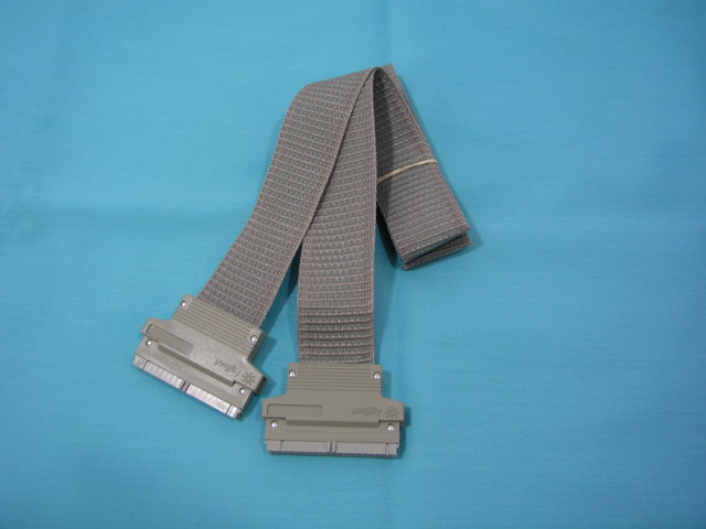
- 01650-61607 16 channel woven probe cable. 40 pin on each end.
- 01650-61608 Adapter with individual flying leads for mini grabbers
- 01650-63203 Termination Adapter (20 pin)
Links
- HP1652B manuals.
- Programming
manual. To control the LA as a data acquisition
device.
- Datasheet of the floppy disk drive.
- Gotek Floppy Drive Emulator.
- File package from Jeff for the 1652B.
- Another example of Sony MFD-52-W10 drive emulation on the HP 9153.
- Running custom 68k code on the HP165X Logic Analyzer
- HP-41 Calculator
page. Some commonality of tools.
(c) 2026 Edward Cheung, all rights reserved.