| Home | Job | Pinball | Photo Album | Automotive | Press/Awards | Contact |

BFT LIBRA-UL-R repair on the Phobos Gate Opener System
Introduction

LIBRA-UL-R controller
After
more than two years of operation, the controller stopped working of the
Phobos BT L system at the
end of 2016. I wrote the
company via the website multiple times,
but received no response. From inspection, it was clear that
the
R23 power resistor (above the bridge heatsink in the previous image)
was burned up. I could not tell the original value, so I had
few options.
Analyzing the schematic
Prior to removing the board, I checked the power supply voltage at the white terminals at the transformer, and measured 33Vac (labelled as 25V on the sticker). Taking the board to my workbench, I was able to power up the board with a 24Vac transformer and could then measure voltages and trace the schematic.

Photo of the solder side of the board. The main driver for the relays is U20 in the middle of the photo (pin 1 is top-right).
Analyzing the schematic
Prior to removing the board, I checked the power supply voltage at the white terminals at the transformer, and measured 33Vac (labelled as 25V on the sticker). Taking the board to my workbench, I was able to power up the board with a 24Vac transformer and could then measure voltages and trace the schematic.
Photo of the solder side of the board. The main driver for the relays is U20 in the middle of the photo (pin 1 is top-right).
I
only traced the Power/IO section of the board. This is the
section most likely to fail and besides, it would be nearly impossible
to find a replacement for U6, the main chip of the logic section.
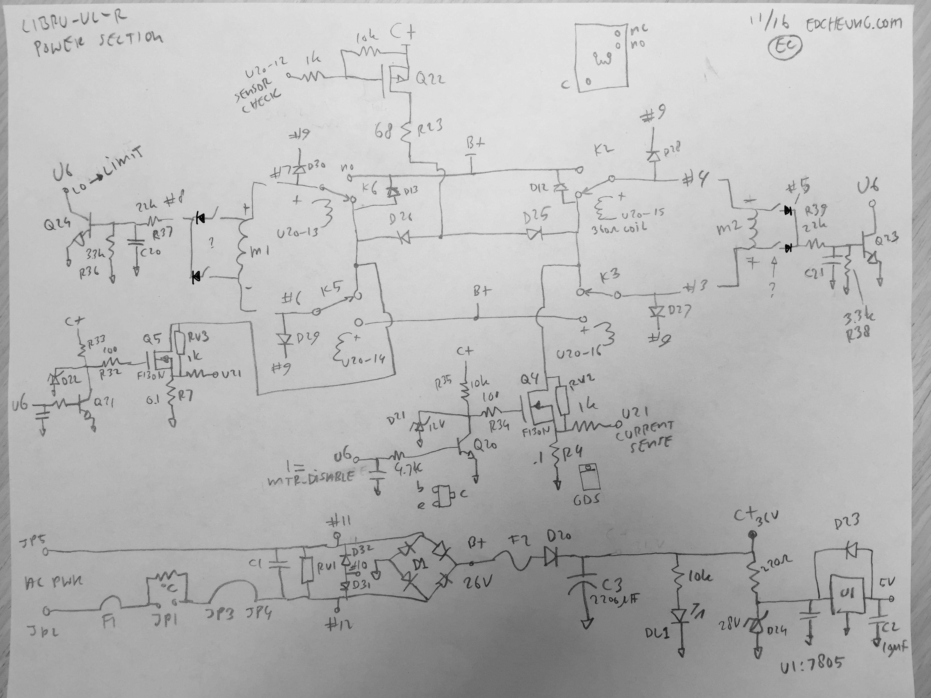
Power Supply Section
Referring to the schematic, we start at the bottom of the page for the power section. Incoming AC power is first filtered by C1 and RV1 and then applied to JP9 terminals #11+12 as the Aux output, and also D1 for full wave rectification. This creates the B+ bus, which is used to power the motor. At an input power of 28Vac, B+ will measure about 26Vdc. D20 isolates B+ from the C+ bus, which is filtered by the C3 2200uF electrolytic capacitor. Due to the filtering, this bus will measure higher, or around 36V in my case. After that, this bus powers the red LED (LD1), and a 28V zener preregulator formed by R30 and D24. This in turn feeds the 5V regulator.
Motor Control Section
I will focus first focus on how Motor2 is powered. Current for this is switched by K2 and K3. When these relay coils are unpowered, the motor is shorted, causing the motor to act as a brake. Throwing K2 (power from U20-15) will cause B+ application to terminal #4 on . If then Q4 is also turned on (via MTR_DISABLE from U6), current will flow through the motor and use R4 as the current sense shunt. Per the note in the Project Log below, the K2 is for the CLOSE function. The opposite occurs when K3 is thrown, and the motor runs in the opposite direction. The circuitry inside the motor and its limit switch is a guess, but I am pretty certain this is correct. It causes the switch output to go to B+ when that switch is closed, which pulls down the open collector output to U6. It is possible that Q4 is run in PWM mode at some point as the manual indicates a slow speed mode.
However an interesting and initially puzzling action occurs before the motor runs. That is when the start/stop button is pushed. The first resulting action is a 30 msec pulse low on the U20-12 pin (Sensor Check). Via Q22, R23 and D25, this applies C+ to both terminals of the motor and Q4 (neither K2+K3 are actuated yet). Initially, Q4 is OFF, but in the middle of the 30 msec pulse, MTR_DISABLE goes low for 10 msec, and that causes about half an amp of current to flow in Q4. This results in about 50mV across R4 for 10 msec, which is routed to the op-amp at U21. My best guess was that this 30 msec pulse is a sensor check, and a later check of the manual shows this to be probably the case (in the "CHECK" section). It causes power to flow to the attached sensors and allows the U6 controller to tell if the system is up against a limit switch, and if the current sensor is working. As an experiment, I shorted the base-emitter junction of Q20, causing the lack of the 50mV pulse. The result was that the motor move was immediately aborted, and none of the relays actuated. This matches what occurs with my original controller with the blown R23 and Q22.
When Q22 is ON, the instantaneous power on R23 is 17W. This resistor is rated for 1W per my inspection. It is unusual for these power resistors to fail shorted (they overheat and open), so my guess is that Q22 failed shorted in the original controller.
Actuation of Motor1 is similar, except power to it is not applied until about 920mseconds after Motor2 runs (this delay is settable in the menu system). This delay allows proper phasing of the gates. The Flasher output is composed by diode ORing all four motor output terminals with diodes D27 through D30, and applied to #9. Current from this feed is returned through steering diodes D31+D32.
The interface from the logic section to the Power/IO section is nine logic lines. Two of them are the MTR_DISABLE lines mentioned above. The remaining seven get buffered by U20. Momentarily jumpering the lowered numbered pins to 5V causes a relay to throw and a motor action to occur. These pins and functions are:
Per the technical manual, the max working current to the motor is 3.5 Amps ("70" on display), and 1.5 Amps nominal ("30" on display). So a good dummy load is about 20 ohms. In the case of my board, repair was not possible so I purchased a new one for $211 (link below). With the new (working) controller in hand, I could better trace the schematic and could now read the value of R23.
Logic Section
The main processor is the H8/3672 from Hitachi. From the hardware manual:
A search shows this chip is not available in retail distributors and needs to be purchased in bulk from sources in Asia. The markings on one of my chips is:
The main chip is connected to a four-digit numeric LCD display with 18 interface pins. I have not been able to find much about it, but it looks like a simple direct multiplexed interface from the processor to the display segments. With 7 segments, a decimal point each, and four digits, the minimum number of pins needed is this sum, or 12. During a move, the display indicates the peak current level of both motors ("Monitoring" section in the manual), in the format "Motor1.Motor2". Each count is 50mA, so a display of '12.00' means 0.6 Amps on Motor 1 and no current on Motor2. The value is held while the move is ongoing, even if the limit switch is hit. The display then goes blank once the move is completed or cancelled.
RF Section
The RF receiver is on a small daughter board that is soldered to the main board via a SIP. The main receiver is either a TDA7210 or a TDA5200, basically a single chip superheterodyne receiver. The JP16 antenna connections route to this board via some small ceramic capacitors. Other than +5V power and ground, there is a "Data Out" line on pin 14, and some kind of ready or signal strength line on pin 13. These two output data lines are buffered by an LM358 dual op-amp in an 8 pin SOIC package. Keying an RF pendant should causes a data stream on pin 14.
Repair Case #1
I was sent a broken unit in August 2020 and was able to repair it. It failed in the same way as ours and I could verify that Q22 was shorted. This would have led to R23 burning open. I was unable to tell much about Q22 and the markings are "AL W72". Based on the resistors around the control pin, I am pretty sure this was originally a MOSFET. However, if you calculate the Vgs, it is a very high value, and I think this would have caused long term stress. This is probably a vulnerability in the design. I addressed that in the repair by changing the resistors around the transistor.

Damaged Q22 transistor.
I decided to build an interface board to help test the controller, which is shown below. It allows me to easily tell if the motor has power and the polarity (red/green LEDs). It also allows me to easily start and stop the motor as you can see in the video. There are also equivalent buttons for the travel limit switches.

The Libra Tester board. Start/Stop button is on the right.
Red / Green LEDs indicate polarity of the motor power and
the switches on the left are the travel limit switches.
Video of repaired Libra (Case #1).

Photo of new MOSFET installed onto the back of the board (middle right).
Note the old FETs is the size of the ones in the bottom left.
New one is much bigger and stronger.
Power Supply Section
Referring to the schematic, we start at the bottom of the page for the power section. Incoming AC power is first filtered by C1 and RV1 and then applied to JP9 terminals #11+12 as the Aux output, and also D1 for full wave rectification. This creates the B+ bus, which is used to power the motor. At an input power of 28Vac, B+ will measure about 26Vdc. D20 isolates B+ from the C+ bus, which is filtered by the C3 2200uF electrolytic capacitor. Due to the filtering, this bus will measure higher, or around 36V in my case. After that, this bus powers the red LED (LD1), and a 28V zener preregulator formed by R30 and D24. This in turn feeds the 5V regulator.
Motor Control Section
I will focus first focus on how Motor2 is powered. Current for this is switched by K2 and K3. When these relay coils are unpowered, the motor is shorted, causing the motor to act as a brake. Throwing K2 (power from U20-15) will cause B+ application to terminal #4 on . If then Q4 is also turned on (via MTR_DISABLE from U6), current will flow through the motor and use R4 as the current sense shunt. Per the note in the Project Log below, the K2 is for the CLOSE function. The opposite occurs when K3 is thrown, and the motor runs in the opposite direction. The circuitry inside the motor and its limit switch is a guess, but I am pretty certain this is correct. It causes the switch output to go to B+ when that switch is closed, which pulls down the open collector output to U6. It is possible that Q4 is run in PWM mode at some point as the manual indicates a slow speed mode.
However an interesting and initially puzzling action occurs before the motor runs. That is when the start/stop button is pushed. The first resulting action is a 30 msec pulse low on the U20-12 pin (Sensor Check). Via Q22, R23 and D25, this applies C+ to both terminals of the motor and Q4 (neither K2+K3 are actuated yet). Initially, Q4 is OFF, but in the middle of the 30 msec pulse, MTR_DISABLE goes low for 10 msec, and that causes about half an amp of current to flow in Q4. This results in about 50mV across R4 for 10 msec, which is routed to the op-amp at U21. My best guess was that this 30 msec pulse is a sensor check, and a later check of the manual shows this to be probably the case (in the "CHECK" section). It causes power to flow to the attached sensors and allows the U6 controller to tell if the system is up against a limit switch, and if the current sensor is working. As an experiment, I shorted the base-emitter junction of Q20, causing the lack of the 50mV pulse. The result was that the motor move was immediately aborted, and none of the relays actuated. This matches what occurs with my original controller with the blown R23 and Q22.
When Q22 is ON, the instantaneous power on R23 is 17W. This resistor is rated for 1W per my inspection. It is unusual for these power resistors to fail shorted (they overheat and open), so my guess is that Q22 failed shorted in the original controller.
Actuation of Motor1 is similar, except power to it is not applied until about 920mseconds after Motor2 runs (this delay is settable in the menu system). This delay allows proper phasing of the gates. The Flasher output is composed by diode ORing all four motor output terminals with diodes D27 through D30, and applied to #9. Current from this feed is returned through steering diodes D31+D32.
The interface from the logic section to the Power/IO section is nine logic lines. Two of them are the MTR_DISABLE lines mentioned above. The remaining seven get buffered by U20. Momentarily jumpering the lowered numbered pins to 5V causes a relay to throw and a motor action to occur. These pins and functions are:
- Motor 2 at +25V (Measured at JP9-3 to JP9-4) / OPEN
- Motor 2 at -25V / CLOSE
- Motor 1 at +25V (Measured at JP9-6 to JP9-7) / OPEN
- Motor 1 at -25V / CLOSE
- Enable Sensor Check (active low)
- Small relay K8 (probably area illumination output on JP9)
- Small relay K4 (probably "Safe" output on JP9 to power light beam devices)
Per the technical manual, the max working current to the motor is 3.5 Amps ("70" on display), and 1.5 Amps nominal ("30" on display). So a good dummy load is about 20 ohms. In the case of my board, repair was not possible so I purchased a new one for $211 (link below). With the new (working) controller in hand, I could better trace the schematic and could now read the value of R23.
Logic Section
The main processor is the H8/3672 from Hitachi. From the hardware manual:
This LSI is equipped with ROM, RAM, an 8-bit timer (TMR), a 16-bit timer, a watchdog timer
(WDT), two types of serial communication interfaces (SCIs), a 10-bit A/D converter, and I/O
ports as on-chip peripheral modules. This LSI is suitable for use as an embedded processor for
high-level control systems. Its on-chip ROM is flash memory that provides
flexibility as it can be reprogrammed in no time to cope with all situations from the early stages of
mass production to full-scale mass production. This is particularly applicable to application
devices with specifications that will most probably change.
A search shows this chip is not available in retail distributors and needs to be purchased in bulk from sources in Asia. The markings on one of my chips is:
64F3672FPV
H8/3672
AJ03959
1138
The
first line is probably the actual part number, and the second line the
generic number. The third line may be some kind of production or batch
code, and I am guessing the last four digits is the date code, which
would make the date of manufacture the 38th week of 2011.H8/3672
AJ03959
1138
The main chip is connected to a four-digit numeric LCD display with 18 interface pins. I have not been able to find much about it, but it looks like a simple direct multiplexed interface from the processor to the display segments. With 7 segments, a decimal point each, and four digits, the minimum number of pins needed is this sum, or 12. During a move, the display indicates the peak current level of both motors ("Monitoring" section in the manual), in the format "Motor1.Motor2". Each count is 50mA, so a display of '12.00' means 0.6 Amps on Motor 1 and no current on Motor2. The value is held while the move is ongoing, even if the limit switch is hit. The display then goes blank once the move is completed or cancelled.
RF Section
The RF receiver is on a small daughter board that is soldered to the main board via a SIP. The main receiver is either a TDA7210 or a TDA5200, basically a single chip superheterodyne receiver. The JP16 antenna connections route to this board via some small ceramic capacitors. Other than +5V power and ground, there is a "Data Out" line on pin 14, and some kind of ready or signal strength line on pin 13. These two output data lines are buffered by an LM358 dual op-amp in an 8 pin SOIC package. Keying an RF pendant should causes a data stream on pin 14.
Repair Case #1
I was sent a broken unit in August 2020 and was able to repair it. It failed in the same way as ours and I could verify that Q22 was shorted. This would have led to R23 burning open. I was unable to tell much about Q22 and the markings are "AL W72". Based on the resistors around the control pin, I am pretty sure this was originally a MOSFET. However, if you calculate the Vgs, it is a very high value, and I think this would have caused long term stress. This is probably a vulnerability in the design. I addressed that in the repair by changing the resistors around the transistor.
Damaged Q22 transistor.
I decided to build an interface board to help test the controller, which is shown below. It allows me to easily tell if the motor has power and the polarity (red/green LEDs). It also allows me to easily start and stop the motor as you can see in the video. There are also equivalent buttons for the travel limit switches.
The Libra Tester board. Start/Stop button is on the right.
Red / Green LEDs indicate polarity of the motor power and
the switches on the left are the travel limit switches.
As
shown above this only tests one of the two motors. I would later
(2021) modify this to add the second motor. This board is used in
Repair Case #2 and later. The added LEDs are orange and yellow
for the other Motor.
Video of repaired Libra (Case #1).
Photo of new MOSFET installed onto the back of the board (middle right).
Note the old FETs is the size of the ones in the bottom left.
New one is much bigger and stronger.
Repair Case #2
This unit was sent to me for repair and I traced it down to a bad U20. I replaced it and the unit worked great afterwards. This was my first time replacing a surface mount integrated circuit and they are very tiny. I think I did a good job with it.
Repair Case #3
This was also sent to me for repair and I traced it back to a bad input MOSFET Q31. Some associated components were also bad. These items are very small, as small as a grain of rice and smaller, but I managed to get them aligned and soldered down.
Repair Case #4
This one had a sensor circuit issue and was quickly repaired. It was also the first time I navigated the board's menu function, performing a factory reset and changing the language to English.
In the light of the Libra being phased out and replaced by
the (much more expensive) Thalia, I think it makes
sense to repair these boards. Send me an email
if you want to have me do it.
This unit was sent to me for repair and I traced it down to a bad U20. I replaced it and the unit worked great afterwards. This was my first time replacing a surface mount integrated circuit and they are very tiny. I think I did a good job with it.

Repair Case #3
This was also sent to me for repair and I traced it back to a bad input MOSFET Q31. Some associated components were also bad. These items are very small, as small as a grain of rice and smaller, but I managed to get them aligned and soldered down.
Repair Case #4
This one had a sensor circuit issue and was quickly repaired. It was also the first time I navigated the board's menu function, performing a factory reset and changing the language to English.
Repair Case #5
This board has an unusual configuration on the power input with regard to location of fusing and power connection. It is also in an auto-close setup, where it waits for a delay after opening and closes if the opto sensor is clear.
Video of Case 5This board has an unusual configuration on the power input with regard to location of fusing and power connection. It is also in an auto-close setup, where it waits for a delay after opening and closes if the opto sensor is clear.
In the light of the Libra being phased out and replaced by
the (much more expensive) Thalia, I think it makes
sense to repair these boards. Send me an email
if you want to have me do it.
Project
Log
- Spring 2014 - BFT dual gate and controller installed
- December 2016 - Gate controller fails and this blog started
- January 2017 - Controller successfully replaced and operators regreased.
- October 2018 - Got an email from Frank W that his single motor system only would open and not CLOSE. With the help of this blog, he tracked it down to a bad K2 relay, and got his system working by swapping it for his K6 relay (he only has a single gate). This proves that K2 is for the CLOSE function.

- April 2019. I have purchased numerous after-market remotes on Ebay and all seem to work well. We prefer the type with the sigle row of buttons. See link below.

- July 2020 - This website states that the Libra has been replaced by the BFT Thalia Board SD 120V. This page was pointed out to me by some emailing me about repair of a Libra. The Thalia does not appear to be a drop-in replacement, and is quite expensive at almost $380. Manual.
- August 5 2020 - The person above was kind enough to send me his unneeded Libra and I was able to repair it and confirm my theories on how this board works (Case #1)
- Feb 2023 - The West gate of the system started to
malfunction. It seemed to occur after a rainfall and the gate
would not open. Close inspection shows that the actuator would
jerk/click upon start. Doing a temporary manual release and then
opening the gate by about 5 degrees would remedy the issue. It
would open and close as long as I did not let the gate fully close (the
problem would repeat if the gate was allowed to close fully). So
to me this told me it was clearly an "open limit" switch issue.
Somehow, the "open limit" was firing as soon as the open command was
given and the actuator/gate was in the fully closed position. The
problem evolved in that it would occur in the morning (when the system
is presumably cold), and then resolve itself by 9am (and things had
warmed up). I resolved to obtain tools to open the actuator to
inspect it, but by that time (a few weeks), the problem stopped
occurring. Other notes: In our system, the West gate is Motor
2. Motor measures about 15 ohms of resistance. Motor will close is
positive power is applied to its red or green wires. See below for an update
- August 6 2023 - I received an email from Alan C with a similar problem:
-
I found your web site whilst googling for some information about a faulty BFT LIBRA that I have.
I noticed that you have repaired many units so are obviously very familiar with these PCBs and their common faults.
- After a few weeks correspondence, the problem appears to be
related to the wires between the Libra and the actuator being wet and
there were open connections that may have been resulting in
shorts. This does not exactly match our fault above as the
actuator state (being within 5 degrees of open) affected the fault.
- Sept 2023 - Tools needed to disassemble actuator arm is 7mm deep socket (9/32" could also be used). Socket needs to be at least 18mm long. Also need a C-clip (snap ring) removal tool to remove arm from gate.

Socket needed to disassemble arm is 7mm deep socket.
In addition, a snap ring removal tool is handy to use
to remove the C-clips and lift the arm out.
- October 2023. Revisited the problem described above from Feb 2023. After a summer of good operation, it started to occur again after a rain storm. I applied silicone to the perimeter of the access door and tape on the body seams to seal the actuator from moisture and added a 4k pull down resistor on the limit switch wire to return reference. That remedied the problem and the system no longer stops after a rain storm. System return is accessible at the loop of R7. The reason I did that was that I suspect the initial application of voltage to the motor bleeds through to the limit switch circuit due to moisture. The 4k load suppresses that pulse. 12/23 Update: Despite heavy rains this fall, the controller link has worked perfectly.
- December 2023. I had been struggling with third party
remote controls for some months. Remotes that used to work
reliably suddenly don't. I also bought many new units on Ebay to
try find a 'good' one (unsuccessfully). This month I obtained a flipper
and one of my first projects was to use it to figure out these
remotes. The results were extremely enlightening. It turns
out that the Libra remote are rolling code type (not surprising), but
these third party remotes are
able to replicate the Libra. Perhaps by sampling a long enough
sequence. However one important thing to note that a press of any
Libra remote will 'roll' the receiver, and the third party remotes will
then need to be reprogrammed. So to use them, you must switch
completely to the third party remotes or any use of a Libra remote will
invalidate their code. This explains our experience as I would be
able to program them, but they would mysteriously stop working after
some random time. Search for remotes on Ebay with "433MHZ,
cloning remote". We prefer the type that are four buttons in a
row so that it is clear which button to push regardless of the
orientation of the remote. These are usually around $2 each,
compared to the authentica Libra remotes, which will run about $20.
Notes on the types of Phobos systems
- Phobos BT - base
- Phobos BT L - long stroke.
This is the one we have.
- 1.8m&250kg / 3m&100kg capacity per datasheet
- Total length is 35.6". Stroke is 10". Min and Max length from axle pin-pin is 22" to 32".
- Phobos BT A - improved version?
- 12'&500kg
- BT A40 may be the successor to BT L
- Phobos BT N - looks similar to the base version
- 1.8m&250kg
- Uses Thalia
controller
- Phobos BT NL - long stroke
- 3m &250kg
- Phobos AC A - high voltage version
Links
- Installation notes for the Phobos system
- Installation manual for the board only
- Replacement board 1 (No longer stocked)
- Replacement board 2 ($400, but photo does not match correct board)
- Thalia Controller (possible replacement, but different pinout)
- Mitto 433Mhz remotes on Ebay.
(c) 2023 Edward Cheung, all rights reserved.