| Home | Job | Pinball | Photo Album | Automotive | Press/Awards | Contact |

How it all started
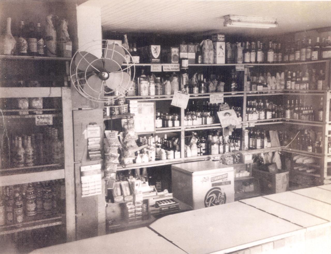
Electronics is a field that has deeply shaped my life and career. It all started in my childhood at my Grandpa's liquor store in San Nicolas, Aruba, called the Fontein Rum Shop. We would often receive promotional items from the cigarette and liquor companies, and one such item was a small Marlboro transistor radio. One day, when I was five or six, I accidentally dropped mine and its cover popped off. Inside I could see the tiny components on a brown board that caused this little box to perform its magical function of allowing me to travel through space (and time) and hearing performances far away. I was completely hooked from that point on.

I found this working unit on Ebay and purchased it for $15 in 2021.
It came with its original paper box.
From that point on, I would read any books I could find about the subject of electricity and science in the local library. I would also collect any parts I could find that I thought were related. These included bits of wire, different types of batteries, bulbs and their holders, etc. My parents bought me various electrical kits, but none were really very sophisticated. They were mainly light bulbs and batteries.

On the right is the Mansur Trading Company (green front with suspended cube)
in Hendrikstraat. Image from Facebook group
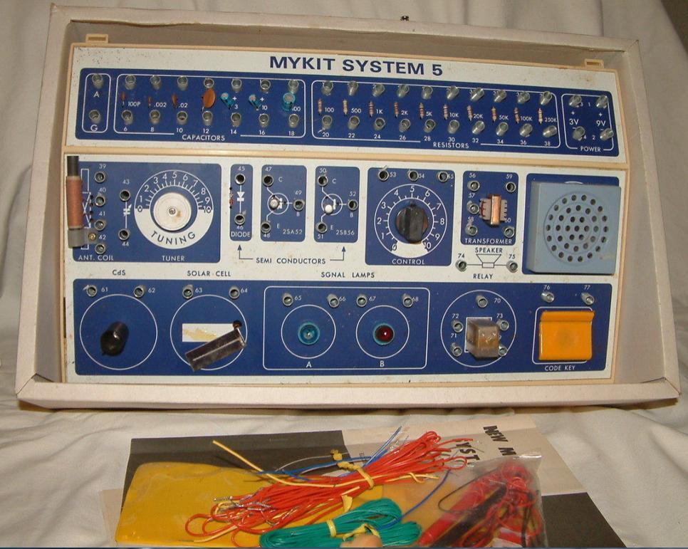
One day when I was about ten years old, things changed when I found an electronics kit at a store near Main Street Oranjestad (probably the Mansur Trading Company). This kit was called the "Mykit System 5" and consisted of real electronics parts that you could connect by using these contact springs. With the included manual, you could wire up all sorts of electronics projects and make them work. Since there was no soldering needed, the configuration could be changed over and over again to make 50 different working projects. These included light flashers, radios, beepers, etc. See here for a table of contents.
Although I had endless fun building the circuits, I frankly did not understand how any of it worked. I understood the basic function of a resistor, light bulb, switch, etc. But the workings of capacitors and transistors were complete mysteries to me.
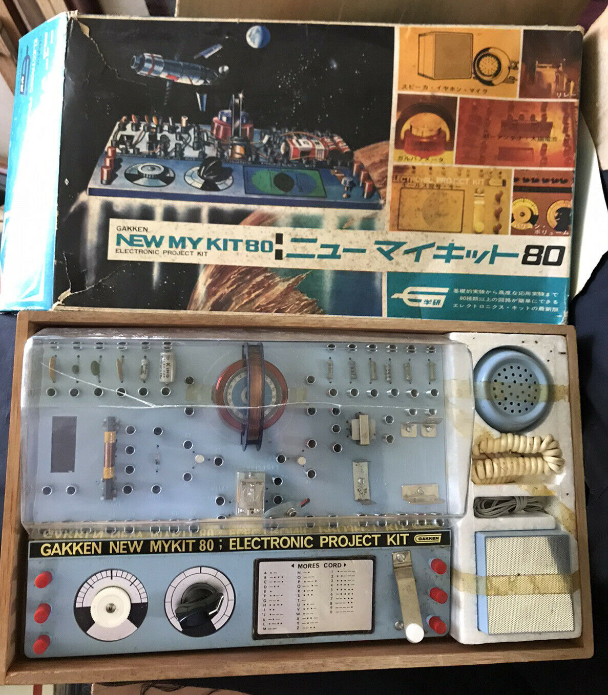
As time went by I collected more of these kits, including the Mykit Junior (above) and the Mykit 80. However, the vulnerability of these kits was the corrosive atmosphere and humidity in Aruba. Gradually, the springs and wires acquired a layer of oxidization, and the usefulness of these kits degraded. In this harsh climate, parts have a limited life unless protected. Over time, I discovered in local book stores such as deWit and Van Dorp, electronics magazines such as Popular Electronics and Radio-Electronics. I subscribed to the latter, and I was able to learn more about simple circuits through this means.
It is in these magazines that I discovered mail-order surplus electronics stores. These showed ads of low cost parts in assortments. I would purchase from places such as Poly Pak's in Lynnfield MA. Shipping time to Aruba was about 1-3 months, so I had to be very patient. It was always great fun when a new shipment arrived.
Other places I purchased from were James Electronics (later changed to Jameco) and Ramsey Electronics.
Naturally, as I accumulated parts and articles, I started to want to build projects. A needed set of items in any electronics lab are the test equipment. These included power supplies, volt meters, frequency counters, scopes, etc. I had none, and little money to buy them, so I decided to build my own. By doing so, I reasoned I would be able to learn along the way.
The first project I decided to build was a frequency counter. This device counts the number of times each second that a signal exceeds some value. For example, if this signal were a digital line, one that switches between two values (logic '0' and '1'), this device will count the number of '0' to '1' transitions (or vice versa). I sent away for the schematics, and when it arrived, I could see it consisted of dozens and dozens of chips. In hindsight, it was clearly much more complicated than I was capable of building. I was undeterred, and proceeded to order the parts from mail order sources.
Per my recollection, the ICs were all from the TTL/74xx family. The block diagram below is very accurate to the design I was trying to build. The Buffer had a MPF102 JFET at the input, whose operation was a mystery to me at the time. The oscillator was a 1Mhz crystal in a can. This signal was divided down a million times to provide a 1 Hz gate signal.
To connect all the parts up, I decided to try my hand at building my own printed circuit (PC) boards. I had only crude tools available of course, but that did not stop me. I started by purchasing blank PC boards. These consisted of a board of fiberglass material onto which is plated/cladded a sheet of copper. Ferric Chloride acid is used to remove the unwanted copper to produce the wiring traces of the board. This is controlled by 'masking' the areas you want to protect with ink or some other substance. The latter is usually applied via a photographic process.
To make the circuit board, I started by obtaining the thinnest and smallest drill bit I could find. This was probably 1/16" (0.062") in diameter, and about twice as large as the proper bit for the pin of an IC (integrated circuit chip). Holding the drill by hand, I drilled out rows of holes onto the blank PC board. Of course, they were not straight as I had no mechanical jigs or asistance. I had probably four or five boards to drill, involving hundreds of holes. After that was done, I took a fresh permanent marker, and drew the interconnecting traces onto the copper material. This formed the protection for the copper I wished to preserve. Following that, I slid the board into a tray of Ferric Chloride acid, and etched away the excess copper. I remember that the bright red copper would turn a purple color as I stirred the acid gently over the board, and then it would gradually thin until the bright white fiberglass material became visible. What remained was the wiring to implement the circuit.
After completing the board set and wiring the chips into the board, I found out that the frequency counter did not work. There were several reasons for this, but the main one was that there was very poor contact between each circuit trace (essentially drawn by the permanent marker) and the pins of the ICs. This is because I had not been able to 'surround' the pin with a copper border, but the trace simply ended at the hole near the pin. The area of mutual contact was very small. I would later learn that the better boards have the barrel of the hole plated with copper as well (once the hole had been drilled) producing a good connection. In addition, I had made a mistake with the numbering order of the pins, and so half of the connections were reversed. The entire project was a disaster, but I sure learned a lot along the process. One of these lessons learned is that the project had to be testable in modules as it is too big a leap to assume that the entire assembly will work on the first try. Having smaller modules tested first helps break the problems down to find their location.
A bigger lab
About a month after I turned 16 we moved from the small house at Orinocostraat 13 where I grew up to a much larger home at Palisiaweg 48 that was designed by my parents. In the bottom level, they set aside a large room for me to be my 'workshop'. I now finally had the space I wanted to build an electronics lab.

My original copy of TAB Books #800.
Master Handbook of 1001 Practical
Electronic Circuits (1977 edition).
I also started to subscribe to the book-of-the-month club by TAB books. This organization sent you one book a month from their technical series, and you could keep it or return it. It turned out that returning books from Aruba was a hassle, so I ended up keeping many of them. One such book for example is the one pictured below, one of the few items that is still around.
Learning from my failed frequency counter project, I scaled back and decided the next project to build would be power supplies. This was natural as I needed a good source of power to run my new creations. I probably picked +5V, +15V, and -15V supplies to build first. These power supplies have several stages, that are similar to the power supplies anyone can buy to power their inexpensive devices such as music players and radios. The first stage is the power transformer, which converts the 120Vac household supply to a lower one such as 9Vac. This alternating current (AC) is then rectified into direct current (DC) by a bridge rectifier. However, this power is pulsing along with the AC power line, so you next need some capacitors to act as storage elements to smooth this pulsing out to a constant DC power. Finally, you need a regulator to adjust the output voltage regardless of fluctuations on the power line or how much current you draw from the power supply. Although potentially a complicated circuit, these regulators were packaged into handy single chip solutions (such as the 78xx series in their familiar TO-220 package), and I used those. I found out while using this newly built power supplies that the regulators could get very hot, a reason that was mystery to me at the time. To take care of this, I bolted the regulators to a copper plate that I had found at the craft shop (handenarbijd klas) at my High School.

A gift from my Uncle Wah Tong was a Dremel
Moto-Tool drill and its drill-press (Model 210).
Image from here.
At 16, an important tool I acquired was a Dremel Moto-Tool drill along with its drill press. With this I could accurately drill small holes. As a guide, I would tape a perforated circuit board to the blank PC board, and mark the holes I needed to drill with a permanent marker. By simply using the grid of holes as a jig, I could make very accurate rows of holes for the PC board. Naturally, all the drilled holes would be in a nice grid pattern. Once done I would then rub dry-transfer IC pads down onto the board to create correct little pads that surrounded the IC pins. I then added the interconnecting traces with my permanent ink pen.
On a trip with my Dad to New York City, I found a store that sold electronic parts and supplies and we purchased a EICO 232 Volt Meter. I was quite happy and proud of it, but I did not know at the time that it could not measure current, nor that it had a vacuum tube pre-amp. The latter feature caused the meter to have very high input resistance, which can be useful in some situations, but not really important for my use. The lack of current measurement was more problematic, but I did not know what I was missing.

The first piece of test equipment my Dad purchased
for me was this EICO 232 voltmeter. It used a tube
amplifier for the input, so it was quite slow in
warming up. It was purchased during a trip he
and I made to New York City.
Image from an Ebay auction.
The second piece of test equipment I decided to build was to revisit the frequency counter project. However, this time I found that there was a single chip that integrated all the functions performed by the dozens of chips (ICM7216). All I needed was a separate LED display. By then I had improved my printed circuit board techniques and this time, the project was successful. After that, I built a voltage to frequency converter, and I could digitally measure voltages by connecting the previous two projects together. Following that, I built an auto-ranging capacitance meter, which worked very well, and represented my first foray into automated (state-machine based) circuitry design. It was wonderful to be able to finally measure the value of any capacitor in my large bin of assorted capacitors by using this meter.
Another piece of test equipment I built was a logic probe with audio output. This is a kind of voltmeter that indicates the status of a digital logic line. This line can take one of two values, each corresponding to a binary bit of information in a logic circuit. By touching this probe to a circuit location, I could tell the state of it from the LED light display. I added two additional features. One was that it could have a tone output: a high tone corresponding to logic "1", and a low tone for logic "0". This way I could tell the value without taking my eyes off the circuit. The second idea was to suspend the logic probe above my head by using a pulley system. I could then reach up and pull it down to use it, and then simply release it to set it aside.
A shocking challenge: design and build a signal oscilloscope
With this small cache of test equipment I decided to tackle something really useful and cool: an Oscilloscope. The idea came to me when I saw a surplus mini 4" diagonal CRT tube at Poly Paks. Once it arrived, I could tell it unfortunately came with no documentation, but I could kind of guess the functions of the connector pins once I visually traced the shiny metal wires inside the glass vacuum tube.
The first problem to tackle in the scope project was obtaining the high-voltage. I learned that to run a CRT, I would need about 1000 Volt (1kV) per inch of diagonal measurement of the screen. That meant about 4000V in my case. After hooking up power to the heater element inside the base of the tube and confirming the glow ("Heater" in image below), I produced a high voltage by ganging in series multiple transformers from the 120Vac power line. It was very simple, and after much nervous experimentation, I produced a fuzzy bright glow in the center of the screen. After some more experimentation with the other pins on the CRT's connector, which lead to the focus elements ("Grid" in the image below), I was able to produce a bright single white dot in the middle of the screen. This was a very important achievement! Now that I had my bright dot, it was time to make it move around on the screen.
From taking apart televisions, I knew that a large set of bell-shaped coils are placed on the neck of the CRT ("Deflection Coils" in image above) to produce a magnetic field to move the dot across the screen. The only yoke I had was from a big 30" television, so I used that. It looked a little funny having this really big yoke on a tiny CRT, but I thought I would give it a try anyway. This "deflection yoke" required a lot of power to run, so as an initial short cut before tackling some transistor amplifier circuits, I connected the output of a low voltage transformer to these coils. This idea was indeed successful in running the yoke, and the dot deflected left-right or up-down (depending on which set of coils in the yoke I used). However, I also received a surprise. The dot was bright only on the ends of the sweep, but not in the middle of the screen. It did not produce a bright stripe across the screen as I had expected.
After some thought I realized why, and it was because the high-voltage was not a constant DC level, but was pulsing since all I did was rectify the stacked transformer outputs to get a pulsing DC voltage. I had not used a filter capacitor to smooth this out. Finding a large value, high voltage capacitor in the mail order resources proved fruitless, so I decided to make my own capacitor. I did this by obtaining a roll of aluminum foil and a roll of clear plastic. These were then rolled up as shown in the diagram below, and then slid into an empty can of Pringles potato chips. I was able to measure the value with my capacitance meter, but I do not recall the value.
Although the capacitor functioned as expected, its value was too low, and it was not sufficient to smooth out the pulsing 4kV high voltage supply. The time between the pulses on the 60Hz line was just too long, and so I had to change the way my high-voltage power supply worked. After much experimentation and searching in articles (before the age of the Internet), I found a power transistor circuit that combined an oscillator and transformer to produce high voltage at a high frequency. This combined with my Pringles can capacitor produced a smooth enough high-voltage to finally give me a white stripe of light on my scope screen.
In the next phase of this project, I focused next on power transistor circuits in order to drive the coils of the deflection yoke. Since I had not yet had the formal education in electronics, I did not know how to properly bias a transistor nor put together an op amp circuit. However, I could rely on ready-designed functional modules from magazine articles or TAB books. So it is with this kind of background that I put together crude voltage-to-current amplifiers that were needed to drive the big coils. As for the grid-lines on the screen, I used a Xerox transparency with the dots and dashes drawn onto it.
In the end these measures did work, and I obtained my functioning scope. However, by then I had learned enough to know that my scope suffered from one big problem. This is that 'real' signal scopes do not use magnetic deflection like televisions do, instead they use electric deflection. This is because the former is slow, and cannot keep up with the high speed signals that are used in logic circuits. I could see audio signals and not too fast digital ones. Nevertheless, the journey was worth it as it provided me hours of fun and experimentation.
There was also a time during the development of the high-voltage supply where I came in contact with the 4000V. It was a painful blow and propelled my body back into some empty card board boxes. I got up with very painful wrist and learned to really respect the high voltage supply.

No longer experimenting on my own
The scope would be my final project on my own at home. At the age of 18, I enrolled at Worcester Polytechnic Institute for a Bachelor's in Science in EE, and left my small lab and cache of parts behind in Aruba. As I finally took Electrical Engineering classes I was able to add the formal knowledge I needed along with the strong intuitive understanding that I had via the learning I did via experimentation. To this day, I still feel I benefit from these early years as I notice that I have a unique ability to look at a circuit and quickly see how it works. Also, I believe my experience building things gives me a good handle at what is practical and feasible.
During my years at WPI, with my improved knowledge, I continued to design and build test equipment such as this chip tester below. This unit allows you to plug in a chip of up to 16 pins, and then access each pin by injecting stimulus with a pulse train or hi/lo level. The status of each of the 16 pins is shown live by a set of 16 LEDs that are multi-colored. The color indicates the level (green:high, red:low, dark: not connected). The tester has a built-in power supply or can take power from a set of banana jacks. It is a similar circuit to my logic probe except now multiplied sixteen times, and with injection of test signals included.

The final project I built in 1983, in the middle of my
years at WPI. It is a chip tester. Only this piece
of test equipment survives the years.

Inside view of the chip tester. The date written onto the circuit board tells me this
was built during the winter break of my sophomore year.
One innovation of the construction is that the lid of the box is itself a PC board. It allows the mounting of electronic parts (such as the IC sockets) right into the lid. The rest of the boards mount in layers underneath, and the entire assembly pops open. The dates on two of the boards are "JAN-5-83". This means I built this tester in Aruba during my winter break of my sophomore year.

MS-230 Miniscope by Non-Linear Systems
In the Spring of 1983, I finally obtained a real scope and purchased a miniature model by Non-Linear Systems. The MS-230 is a small unit that can be battery powered. It has a 30 Mhz bandwidth and dual traces. Over the years, I have had to replace the batteries several times, but it was still working perfectly (after cleaning of the switch contacts and new batteries) in September 2016, almost 35 years after purchase.
I have put science instruments and electronic systems into space and looking back I really think my years of experimentation has helped me greatly in my career. It was certainly a lot of fun to learn and build these projects
Electronics is a field that has deeply shaped my life and career. It all started in my childhood at my Grandpa's liquor store in San Nicolas, Aruba, called the Fontein Rum Shop. We would often receive promotional items from the cigarette and liquor companies, and one such item was a small Marlboro transistor radio. One day, when I was five or six, I accidentally dropped mine and its cover popped off. Inside I could see the tiny components on a brown board that caused this little box to perform its magical function of allowing me to travel through space (and time) and hearing performances far away. I was completely hooked from that point on.
I found this working unit on Ebay and purchased it for $15 in 2021.
It came with its original paper box.
From that point on, I would read any books I could find about the subject of electricity and science in the local library. I would also collect any parts I could find that I thought were related. These included bits of wire, different types of batteries, bulbs and their holders, etc. My parents bought me various electrical kits, but none were really very sophisticated. They were mainly light bulbs and batteries.
On the right is the Mansur Trading Company (green front with suspended cube)
in Hendrikstraat. Image from Facebook group
One day when I was about ten years old, things changed when I found an electronics kit at a store near Main Street Oranjestad (probably the Mansur Trading Company). This kit was called the "Mykit System 5" and consisted of real electronics parts that you could connect by using these contact springs. With the included manual, you could wire up all sorts of electronics projects and make them work. Since there was no soldering needed, the configuration could be changed over and over again to make 50 different working projects. These included light flashers, radios, beepers, etc. See here for a table of contents.

Although I had endless fun building the circuits, I frankly did not understand how any of it worked. I understood the basic function of a resistor, light bulb, switch, etc. But the workings of capacitors and transistors were complete mysteries to me.

As time went by I collected more of these kits, including the Mykit Junior (above) and the Mykit 80. However, the vulnerability of these kits was the corrosive atmosphere and humidity in Aruba. Gradually, the springs and wires acquired a layer of oxidization, and the usefulness of these kits degraded. In this harsh climate, parts have a limited life unless protected. Over time, I discovered in local book stores such as deWit and Van Dorp, electronics magazines such as Popular Electronics and Radio-Electronics. I subscribed to the latter, and I was able to learn more about simple circuits through this means.
It is in these magazines that I discovered mail-order surplus electronics stores. These showed ads of low cost parts in assortments. I would purchase from places such as Poly Pak's in Lynnfield MA. Shipping time to Aruba was about 1-3 months, so I had to be very patient. It was always great fun when a new shipment arrived.

Other places I purchased from were James Electronics (later changed to Jameco) and Ramsey Electronics.
Naturally, as I accumulated parts and articles, I started to want to build projects. A needed set of items in any electronics lab are the test equipment. These included power supplies, volt meters, frequency counters, scopes, etc. I had none, and little money to buy them, so I decided to build my own. By doing so, I reasoned I would be able to learn along the way.
The first project I decided to build was a frequency counter. This device counts the number of times each second that a signal exceeds some value. For example, if this signal were a digital line, one that switches between two values (logic '0' and '1'), this device will count the number of '0' to '1' transitions (or vice versa). I sent away for the schematics, and when it arrived, I could see it consisted of dozens and dozens of chips. In hindsight, it was clearly much more complicated than I was capable of building. I was undeterred, and proceeded to order the parts from mail order sources.
Per my recollection, the ICs were all from the TTL/74xx family. The block diagram below is very accurate to the design I was trying to build. The Buffer had a MPF102 JFET at the input, whose operation was a mystery to me at the time. The oscillator was a 1Mhz crystal in a can. This signal was divided down a million times to provide a 1 Hz gate signal.

To connect all the parts up, I decided to try my hand at building my own printed circuit (PC) boards. I had only crude tools available of course, but that did not stop me. I started by purchasing blank PC boards. These consisted of a board of fiberglass material onto which is plated/cladded a sheet of copper. Ferric Chloride acid is used to remove the unwanted copper to produce the wiring traces of the board. This is controlled by 'masking' the areas you want to protect with ink or some other substance. The latter is usually applied via a photographic process.
To make the circuit board, I started by obtaining the thinnest and smallest drill bit I could find. This was probably 1/16" (0.062") in diameter, and about twice as large as the proper bit for the pin of an IC (integrated circuit chip). Holding the drill by hand, I drilled out rows of holes onto the blank PC board. Of course, they were not straight as I had no mechanical jigs or asistance. I had probably four or five boards to drill, involving hundreds of holes. After that was done, I took a fresh permanent marker, and drew the interconnecting traces onto the copper material. This formed the protection for the copper I wished to preserve. Following that, I slid the board into a tray of Ferric Chloride acid, and etched away the excess copper. I remember that the bright red copper would turn a purple color as I stirred the acid gently over the board, and then it would gradually thin until the bright white fiberglass material became visible. What remained was the wiring to implement the circuit.
After completing the board set and wiring the chips into the board, I found out that the frequency counter did not work. There were several reasons for this, but the main one was that there was very poor contact between each circuit trace (essentially drawn by the permanent marker) and the pins of the ICs. This is because I had not been able to 'surround' the pin with a copper border, but the trace simply ended at the hole near the pin. The area of mutual contact was very small. I would later learn that the better boards have the barrel of the hole plated with copper as well (once the hole had been drilled) producing a good connection. In addition, I had made a mistake with the numbering order of the pins, and so half of the connections were reversed. The entire project was a disaster, but I sure learned a lot along the process. One of these lessons learned is that the project had to be testable in modules as it is too big a leap to assume that the entire assembly will work on the first try. Having smaller modules tested first helps break the problems down to find their location.
A bigger lab
About a month after I turned 16 we moved from the small house at Orinocostraat 13 where I grew up to a much larger home at Palisiaweg 48 that was designed by my parents. In the bottom level, they set aside a large room for me to be my 'workshop'. I now finally had the space I wanted to build an electronics lab.
My original copy of TAB Books #800.
Master Handbook of 1001 Practical
Electronic Circuits (1977 edition).
I also started to subscribe to the book-of-the-month club by TAB books. This organization sent you one book a month from their technical series, and you could keep it or return it. It turned out that returning books from Aruba was a hassle, so I ended up keeping many of them. One such book for example is the one pictured below, one of the few items that is still around.
Learning from my failed frequency counter project, I scaled back and decided the next project to build would be power supplies. This was natural as I needed a good source of power to run my new creations. I probably picked +5V, +15V, and -15V supplies to build first. These power supplies have several stages, that are similar to the power supplies anyone can buy to power their inexpensive devices such as music players and radios. The first stage is the power transformer, which converts the 120Vac household supply to a lower one such as 9Vac. This alternating current (AC) is then rectified into direct current (DC) by a bridge rectifier. However, this power is pulsing along with the AC power line, so you next need some capacitors to act as storage elements to smooth this pulsing out to a constant DC power. Finally, you need a regulator to adjust the output voltage regardless of fluctuations on the power line or how much current you draw from the power supply. Although potentially a complicated circuit, these regulators were packaged into handy single chip solutions (such as the 78xx series in their familiar TO-220 package), and I used those. I found out while using this newly built power supplies that the regulators could get very hot, a reason that was mystery to me at the time. To take care of this, I bolted the regulators to a copper plate that I had found at the craft shop (handenarbijd klas) at my High School.
A gift from my Uncle Wah Tong was a Dremel
Moto-Tool drill and its drill-press (Model 210).
Image from here.
At 16, an important tool I acquired was a Dremel Moto-Tool drill along with its drill press. With this I could accurately drill small holes. As a guide, I would tape a perforated circuit board to the blank PC board, and mark the holes I needed to drill with a permanent marker. By simply using the grid of holes as a jig, I could make very accurate rows of holes for the PC board. Naturally, all the drilled holes would be in a nice grid pattern. Once done I would then rub dry-transfer IC pads down onto the board to create correct little pads that surrounded the IC pins. I then added the interconnecting traces with my permanent ink pen.

On a trip with my Dad to New York City, I found a store that sold electronic parts and supplies and we purchased a EICO 232 Volt Meter. I was quite happy and proud of it, but I did not know at the time that it could not measure current, nor that it had a vacuum tube pre-amp. The latter feature caused the meter to have very high input resistance, which can be useful in some situations, but not really important for my use. The lack of current measurement was more problematic, but I did not know what I was missing.
The first piece of test equipment my Dad purchased
for me was this EICO 232 voltmeter. It used a tube
amplifier for the input, so it was quite slow in
warming up. It was purchased during a trip he
and I made to New York City.
Image from an Ebay auction.
The second piece of test equipment I decided to build was to revisit the frequency counter project. However, this time I found that there was a single chip that integrated all the functions performed by the dozens of chips (ICM7216). All I needed was a separate LED display. By then I had improved my printed circuit board techniques and this time, the project was successful. After that, I built a voltage to frequency converter, and I could digitally measure voltages by connecting the previous two projects together. Following that, I built an auto-ranging capacitance meter, which worked very well, and represented my first foray into automated (state-machine based) circuitry design. It was wonderful to be able to finally measure the value of any capacitor in my large bin of assorted capacitors by using this meter.
Another piece of test equipment I built was a logic probe with audio output. This is a kind of voltmeter that indicates the status of a digital logic line. This line can take one of two values, each corresponding to a binary bit of information in a logic circuit. By touching this probe to a circuit location, I could tell the state of it from the LED light display. I added two additional features. One was that it could have a tone output: a high tone corresponding to logic "1", and a low tone for logic "0". This way I could tell the value without taking my eyes off the circuit. The second idea was to suspend the logic probe above my head by using a pulley system. I could then reach up and pull it down to use it, and then simply release it to set it aside.
A shocking challenge: design and build a signal oscilloscope
With this small cache of test equipment I decided to tackle something really useful and cool: an Oscilloscope. The idea came to me when I saw a surplus mini 4" diagonal CRT tube at Poly Paks. Once it arrived, I could tell it unfortunately came with no documentation, but I could kind of guess the functions of the connector pins once I visually traced the shiny metal wires inside the glass vacuum tube.

The first problem to tackle in the scope project was obtaining the high-voltage. I learned that to run a CRT, I would need about 1000 Volt (1kV) per inch of diagonal measurement of the screen. That meant about 4000V in my case. After hooking up power to the heater element inside the base of the tube and confirming the glow ("Heater" in image below), I produced a high voltage by ganging in series multiple transformers from the 120Vac power line. It was very simple, and after much nervous experimentation, I produced a fuzzy bright glow in the center of the screen. After some more experimentation with the other pins on the CRT's connector, which lead to the focus elements ("Grid" in the image below), I was able to produce a bright single white dot in the middle of the screen. This was a very important achievement! Now that I had my bright dot, it was time to make it move around on the screen.

From taking apart televisions, I knew that a large set of bell-shaped coils are placed on the neck of the CRT ("Deflection Coils" in image above) to produce a magnetic field to move the dot across the screen. The only yoke I had was from a big 30" television, so I used that. It looked a little funny having this really big yoke on a tiny CRT, but I thought I would give it a try anyway. This "deflection yoke" required a lot of power to run, so as an initial short cut before tackling some transistor amplifier circuits, I connected the output of a low voltage transformer to these coils. This idea was indeed successful in running the yoke, and the dot deflected left-right or up-down (depending on which set of coils in the yoke I used). However, I also received a surprise. The dot was bright only on the ends of the sweep, but not in the middle of the screen. It did not produce a bright stripe across the screen as I had expected.
After some thought I realized why, and it was because the high-voltage was not a constant DC level, but was pulsing since all I did was rectify the stacked transformer outputs to get a pulsing DC voltage. I had not used a filter capacitor to smooth this out. Finding a large value, high voltage capacitor in the mail order resources proved fruitless, so I decided to make my own capacitor. I did this by obtaining a roll of aluminum foil and a roll of clear plastic. These were then rolled up as shown in the diagram below, and then slid into an empty can of Pringles potato chips. I was able to measure the value with my capacitance meter, but I do not recall the value.

Although the capacitor functioned as expected, its value was too low, and it was not sufficient to smooth out the pulsing 4kV high voltage supply. The time between the pulses on the 60Hz line was just too long, and so I had to change the way my high-voltage power supply worked. After much experimentation and searching in articles (before the age of the Internet), I found a power transistor circuit that combined an oscillator and transformer to produce high voltage at a high frequency. This combined with my Pringles can capacitor produced a smooth enough high-voltage to finally give me a white stripe of light on my scope screen.
In the next phase of this project, I focused next on power transistor circuits in order to drive the coils of the deflection yoke. Since I had not yet had the formal education in electronics, I did not know how to properly bias a transistor nor put together an op amp circuit. However, I could rely on ready-designed functional modules from magazine articles or TAB books. So it is with this kind of background that I put together crude voltage-to-current amplifiers that were needed to drive the big coils. As for the grid-lines on the screen, I used a Xerox transparency with the dots and dashes drawn onto it.
In the end these measures did work, and I obtained my functioning scope. However, by then I had learned enough to know that my scope suffered from one big problem. This is that 'real' signal scopes do not use magnetic deflection like televisions do, instead they use electric deflection. This is because the former is slow, and cannot keep up with the high speed signals that are used in logic circuits. I could see audio signals and not too fast digital ones. Nevertheless, the journey was worth it as it provided me hours of fun and experimentation.
There was also a time during the development of the high-voltage supply where I came in contact with the 4000V. It was a painful blow and propelled my body back into some empty card board boxes. I got up with very painful wrist and learned to really respect the high voltage supply.
In my lab at Palisiaweg
just before leaving for college.
You can see the EICO meter on the right. Between it
and me you can see my home-built scope. The black
box with the red lettering is the control panel (by my elbow).
You can also see my older Mykit experimenter kits on the shelf,
including the first one, the Mykit System 5.
You can see the EICO meter on the right. Between it
and me you can see my home-built scope. The black
box with the red lettering is the control panel (by my elbow).
You can also see my older Mykit experimenter kits on the shelf,
including the first one, the Mykit System 5.
No longer experimenting on my own
The scope would be my final project on my own at home. At the age of 18, I enrolled at Worcester Polytechnic Institute for a Bachelor's in Science in EE, and left my small lab and cache of parts behind in Aruba. As I finally took Electrical Engineering classes I was able to add the formal knowledge I needed along with the strong intuitive understanding that I had via the learning I did via experimentation. To this day, I still feel I benefit from these early years as I notice that I have a unique ability to look at a circuit and quickly see how it works. Also, I believe my experience building things gives me a good handle at what is practical and feasible.
During my years at WPI, with my improved knowledge, I continued to design and build test equipment such as this chip tester below. This unit allows you to plug in a chip of up to 16 pins, and then access each pin by injecting stimulus with a pulse train or hi/lo level. The status of each of the 16 pins is shown live by a set of 16 LEDs that are multi-colored. The color indicates the level (green:high, red:low, dark: not connected). The tester has a built-in power supply or can take power from a set of banana jacks. It is a similar circuit to my logic probe except now multiplied sixteen times, and with injection of test signals included.
The final project I built in 1983, in the middle of my
years at WPI. It is a chip tester. Only this piece
of test equipment survives the years.
I
tested to see if this chip tester still worked during the writing of
this page in 2015, and it
still powered up and worked. More than 30 years after its
home-made construction.
Inside view of the chip tester. The date written onto the circuit board tells me this
was built during the winter break of my sophomore year.
One innovation of the construction is that the lid of the box is itself a PC board. It allows the mounting of electronic parts (such as the IC sockets) right into the lid. The rest of the boards mount in layers underneath, and the entire assembly pops open. The dates on two of the boards are "JAN-5-83". This means I built this tester in Aruba during my winter break of my sophomore year.
MS-230 Miniscope by Non-Linear Systems
In the Spring of 1983, I finally obtained a real scope and purchased a miniature model by Non-Linear Systems. The MS-230 is a small unit that can be battery powered. It has a 30 Mhz bandwidth and dual traces. Over the years, I have had to replace the batteries several times, but it was still working perfectly (after cleaning of the switch contacts and new batteries) in September 2016, almost 35 years after purchase.
I have put science instruments and electronic systems into space and looking back I really think my years of experimentation has helped me greatly in my career. It was certainly a lot of fun to learn and build these projects
| In January 2016, one of my High School teachers passed
away and I wrote about his influence on my life on Facebook:
Despite fuzzy memories and stereotypes, I was never more than an average student in High School at Colegio Arubano. I never got good grades and just got by. That changed in the last two years of VWO when I took Wiskunde II with Meneer Pronk. I would later learn that this subject is called "Linear Algebra". During the course of this class I started to actually visualize mathematics. Instead of seeing equations and words on a page, I started to see in my mind the 3-D objects that these represented. I could solve problems now by visualizing them in my head. It was an amazing transformation from how I viewed school work before. This had a side effect in all my other classes, and I got much better at the other math courses and I started to realize I really liked "Natuurkunde" (Physics). I went from an ok student to graduating second in my class. The ability I learned in his class continued to carry me through my University years until I finished my doctorate. I have now worked inside the Space Shuttle, flown in Zero Gravity, and built cameras that are now on the Hubble Space Telescope, but I will never forget how much my life was shaped by Meneer Pronk's class. After 35 years, I still have my school books of that class. A few years ago, I was hosting the Green Aruba 4 conference and he came to a social function. I was so pleased to tell him how important that class was to me, and it was really great to see him. Thank you Meneer Pronk for your guidance and your class of Wiskunde II. May you rest in peace.
|
