| Home | Job | Pinball | Photo Album | Automotive | Press/Awards | Contact |

Sensor-Based Motion Planning of Robotic Arm Manipulators
Motion control of robotic arms with sensor skin informationWork at Yale
In 1985, after graduating from WPI, I transferred to Yale University. Once there, one of the first classes I took was with Prof. Vladimir Lumelsky in the robotics/electrical engineering department. That fall, he had just started his professorship after working at General Electric's robotics department. Prof. Lumelsky's research direction was motion planning of wheeled vehicles or arm manipulators, and he was looking for a student with hardware experience. I was soon building sensor circuits and running the GE P5 robot arm he brought from his previous post.
Prof. Lumelsky described to me that he wanted someone to help him build a sensor 'skin' for a robotic arm, which would allow it to maneuver and move around in a cluttered and unknown environment. This had not been done before in the field of robotics, and would be a great way to work on my dissertation.

The first proximity sensor array prototype.

A closeup of the acrylic strip that holds the optical components. The
emitter is in the exposed black hole, and the receiver is covered by
red tape to cut down on ambient light.
I started by building a sensor array arranged in a single line. The components were mounted on standard printed circuit board material, and a black acrylic strip functioned as the means to mount the emitter-receiver pair, preventing direct coupling of light. This was then placed on the surface of a PUMA 560 robot arm, and the motion of the arm limited to a plane. In this two dimensional arrangement, the sensor system could detect obstacles that obstructed the motion of the arm.

The linear array sensor mounted on a PUMA robot arm.

Almost the entire perimeter of the arm is covered including the tip of the arm.
Our first paper describing this work was an internal technical report of the Electrical Engineering department.
Later that year, we edited this paper and published it at the 1988 IEEE International Conference of Robotics and Automation (ICRA-88), which took place in Philadelphia, PA.
We then took this paper through the peer review process and it was published with several edits in the IEEE robotics journal.
I spent the summer of 1988 at the Philips Labs in Briarcliff Manor, NY, under the direction of Dr. Leo Dorst. Prof. Lumelsky had a research agreement with this facility, and I used the PUMA robot arm that was there for the installation of the linear sensor array. I then wrote the software to move the arm under closed-loop sensor control around an unknown environment.
Having completed the work in 2D, where we use only two joints of the arm to restrict its motion to a plane, I now had to find a way to wrap the entire surface of a robot arm in proximity sensors, and perform the same work in full three-dimensional space.

The two dimensional sensor array was built using flex
circuit board material.
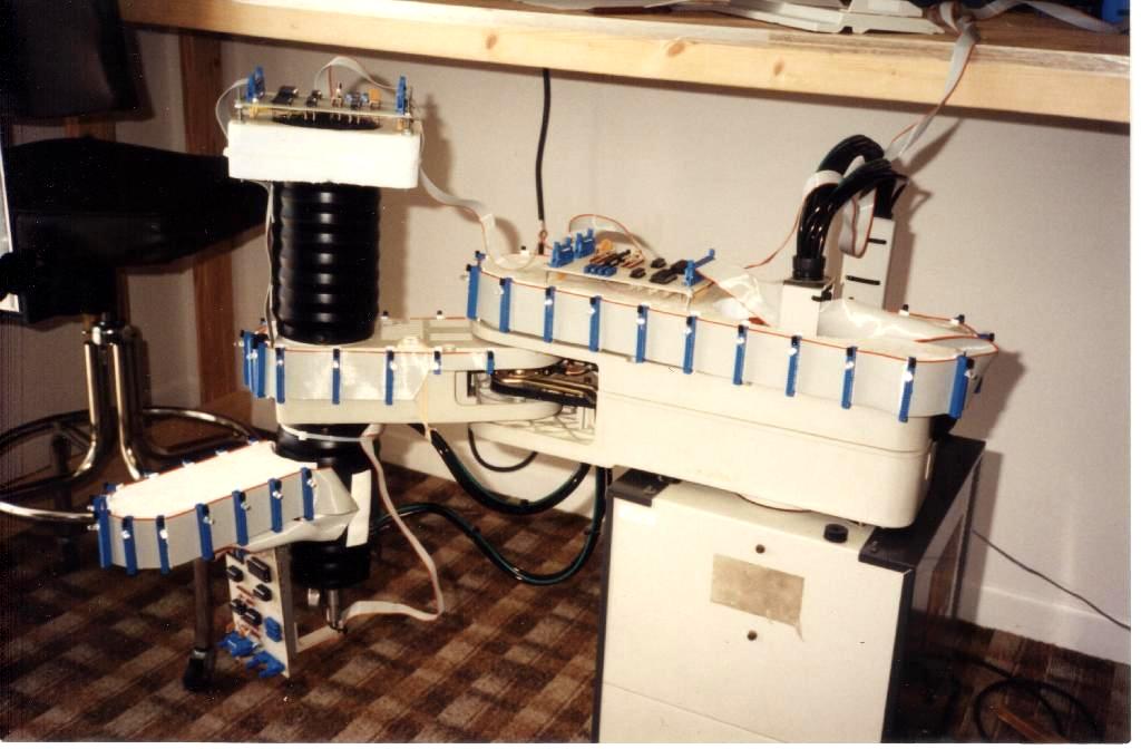
The approach I thought of was to build the sensor skin out of flexible circuit board material, and fasten this to the arm. This substrate would allow both electrical connection of the circuitry as well as mechanical support. I drew the artwork for the circuit board on my Macintosh computer, ordered the board, and built the sensor.

Close-up view of the sensor skin. One can see the electro-optical components.
The flex circuit board was built by Bar-Pat, Inc in Bridgeport, CT.

One complicated part of the skin was the main elbow joint of the P5 robot.
Near the bottom of this image, one can also see the cable connecting the sensor array.
By using a serial protocol, the cable is very slender and easy to manage.
The hardware details of this skin was published in an internal technical report.
This paper became my submission to ICRA-89, held in Scottsdale Arizona.
It was at this conference that I met Dr. Daniel Wegerif, who worked at the McDonnell Douglas Space Systems at the Kennedy Space Center. He thought my research would be very useful to NASA, and was very interested in it. We would continue our contacts in the coming years (update below).

In addition to the P5 arm, one can see here an input device next to
my elbow that was built to do this research. Its kinematic structure
matches the robot arm's so that a user can move the big arm in an
intuitive manner by handling the small one.
Of course, the sensitive skin is not useful without an algorithm to use this data for motion planning of the entire arm, and I developed that next and it was described in our next technical report.
We then took this paper to ICRA-90, held in Cincinnati Ohio.
I spent the summer of 1989 at Philips Labs one more time, and this time worked on making an integrated circuit chip that would miniaturize the proximity sensor circuit into a single microchip. They fabricated this onto a semiconductor wafer, but the project was terminated due to lack of funding. I still have one of these manufactured wafers today.

Plot of the microchip we made at the Philips Lab along
with one of the manufactured silicon wafers.
Over
the course of the the
next year, we made improvements and augmentations to the motion control
algorithm that uses the entire skin of sensors. The
improvements
included an algorithm
that followed the commands from a Mini-Master handcontroller unless an
obstacle was encountered. This controller matches the
kinematic
structure of the P5 arm, and creates a situation where the user can
very intuitively command the big arm. If an obstacle was
encountered, the arm then stopped and performed a
sliding motion along the obstacle (in a non-contact sense) to best
comply with the commands. In this simple control algorithm,
it
was not always
possible to autonomously find a path around the obstruction, but the
arm would
always move in a 'safe' manner. The operator would then use
his/her view of the workspace to work out an overall path.

I called the input device the "Mini-Master". An algorithm was developed to have the
big arm follow the little one unless an obstacle was encountered.
Another
mode that is contained in the previous algorithm is one I called
"repeller
mode". If the environment moved in the direction of the arm,
it
could 'push' (in a non-contact sense) the arm around. This
became
one of my favorite ways of putting the arm into a desired configuration
during setting up of robot experiments: I would simply push the
arm into place.
However, these two functions were ancillary to the main operating mode I developed as part of my dissertation. In this mode, the algorithm (using the skin sensor) autonomously searches the work space for a path from a starting point to a desired end point. Although this seems easy at first glance, it had been Prof. Lumelsky's findings in his prior research that there is not always an intuitive solution.
One way Prof. Lumelsky illustrated this to others was to have one of his students develop a type of video game where a visitor is asked to move a robot arm through a cluttered environment using only skin sensor information. Inevitably, the visitor would find it difficult to find a path in a time shorter than the automatic algorithm.

Prof. Lumelsky is here inside the robot workspace, and I (in the background)
am handling the Mini-Master to move the arm around him and obstacles.
We published a description of these algorithms in an internal technical report.
We reedited this paper, and submitted it to ICRA-91, held in Sacramento, CA.
Finally, to sum it all up, I published my doctoral dissertation in 1991. It was the culmination of the work over the past several years.
I wrote much of this thesis while working at the Kennedy Space Center in the summer of 1990. Dan Wegerif had obtained a summer position for me at McDonnell Douglas, and we worked on a study to understand the amount of time the International Space Station would need to be serviced by astronaut crew once it was completed. It made a strong case for robotic servicing in space.
Video of the sensitive skin project.
My thesis was subsequently reedited and tailored for publication in the following forms:
The years I spent at Yale were a great learning experience, and I am grateful to my mentor Professor Vladimir Lumelsky. Shortly after I left Yale in 1991, he took another post at the University of Wisconsin, and continued his research there. Then in 2004, he moved (coincidentally) to the Goddard Space Flight Center and retired in 2012 from there.
Moving to NASA
Thanks to Dan Wegerif, my work at KSC led me in 1991 to a post at the Goddard Space Flight Center (GSFC), where I started working at the robotics lab in the high bay of Building 11. At the time, NASA was building the Flight Telerobotic Servicer (FTS), which was to be a compliment to the SPDM robot built by the Canadian Space Agency.
At GSFC, I switched from optical proximity sensors to a capacitance-based sensor developed by John Vranish and Lou Palumbo, called "Capaciflectors". I made several improvements on this sensor, and used them in an array fashion as I did with the optical ones.

Among the manipulators in the lab were two 1607 arms from the
Robotics Research Corporation (RRC).

Close-up of the WAM/WAF end-effector of the RRC arm. It is one that can
quick connect to a complimentary half, and has connectors
that mate electrical circuits.
We used the Capaciflector for obstacle detection and avoidance, and also in applications requiring careful alignment between the robot and its environment. One example is the Worksite Attachment Mechanism/Worksite Attachment Fixture (WAM/WAF) end-effector that was developed by John Vranish. In this application, we applied copper strips to the WAM/WAF, and wrote algorithms for it to be able to locate, center and mate to its other half. In this manner, it could pick up tools, and perform robotic tasks.
A video showing the GSFC robot at work with its Capaciflectors.
Another example is shown in the above video where we put Capaciflectors on the tool of the robot. The tool in this case is a 7/16" nutdriver, which is standard on the Hubble Space Telescope (HST). The system uses the Capaciflectors to locate and open the latches on a container meant for astronaut use. This container, known as the Small ORU Protective Enclosure (SOPE), is how HST components are flown into space. The robot in this case assists the astronaut crew by opening up containers and prepares the worksite for use.

Mosaicked image of the SOPE task experiment.
During these years, we published several papers, including:
Servicing Aid Tool
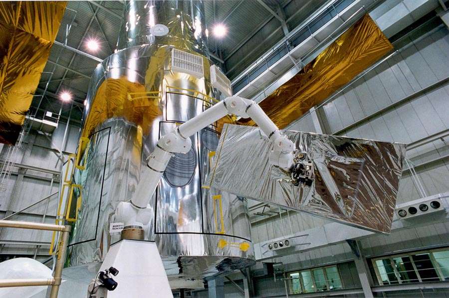
In the late 1990s, I was on the development team of a robot arm that would be used to potentially assist the two space walking astronauts during a Hubble Servicing Mission. The arm was built by the Robotics Research Corporation (RRC) in Ohio. During the space walks, one of the astronauts rides the end of the large RMS arm, and the other is a 'free-floater' that assists the main astronaut. The concept of the SAT was to act as a second arm to ferry parts between the astronauts. So while one was on Hubble preparing the work site, the other could retrieve tools or new instruments to be installed.
The ultimate demonstration test was run at the full-scale Space Shuttle and Hubble simulator facility shown above (now no longer exists). The SAT is holding a simulated science instrument, and during this test was controlled from the simulated aft flight deck. Although the test was a success, the concept was not pursued any further.
In 1985, after graduating from WPI, I transferred to Yale University. Once there, one of the first classes I took was with Prof. Vladimir Lumelsky in the robotics/electrical engineering department. That fall, he had just started his professorship after working at General Electric's robotics department. Prof. Lumelsky's research direction was motion planning of wheeled vehicles or arm manipulators, and he was looking for a student with hardware experience. I was soon building sensor circuits and running the GE P5 robot arm he brought from his previous post.
Prof. Lumelsky described to me that he wanted someone to help him build a sensor 'skin' for a robotic arm, which would allow it to maneuver and move around in a cluttered and unknown environment. This had not been done before in the field of robotics, and would be a great way to work on my dissertation.
The first proximity sensor array prototype.
A closeup of the acrylic strip that holds the optical components. The
emitter is in the exposed black hole, and the receiver is covered by
red tape to cut down on ambient light.
I started by building a sensor array arranged in a single line. The components were mounted on standard printed circuit board material, and a black acrylic strip functioned as the means to mount the emitter-receiver pair, preventing direct coupling of light. This was then placed on the surface of a PUMA 560 robot arm, and the motion of the arm limited to a plane. In this two dimensional arrangement, the sensor system could detect obstacles that obstructed the motion of the arm.
The linear array sensor mounted on a PUMA robot arm.
Almost the entire perimeter of the arm is covered including the tip of the arm.
Our first paper describing this work was an internal technical report of the Electrical Engineering department.
E.Cheung
and V. Lumelsky, Proximity Sensing in Robot Manipulator
Motion Planning: System and Implementation Issues, Technical
Report No.
8802, Center for Systems Science, Yale University
Later that year, we edited this paper and published it at the 1988 IEEE International Conference of Robotics and Automation (ICRA-88), which took place in Philadelphia, PA.
E.
Cheung and V. Lumelsky, Motion Planning for Robot Arm
Manipulators
with Proximity Sensors, Proc. 1988
IEEE Conference on Robotics and Automation, Philadelphia ,
PA
We then took this paper through the peer review process and it was published with several edits in the IEEE robotics journal.
I spent the summer of 1988 at the Philips Labs in Briarcliff Manor, NY, under the direction of Dr. Leo Dorst. Prof. Lumelsky had a research agreement with this facility, and I used the PUMA robot arm that was there for the installation of the linear sensor array. I then wrote the software to move the arm under closed-loop sensor control around an unknown environment.
Having completed the work in 2D, where we use only two joints of the arm to restrict its motion to a plane, I now had to find a way to wrap the entire surface of a robot arm in proximity sensors, and perform the same work in full three-dimensional space.
The two dimensional sensor array was built using flex
circuit board material.
The approach I thought of was to build the sensor skin out of flexible circuit board material, and fasten this to the arm. This substrate would allow both electrical connection of the circuitry as well as mechanical support. I drew the artwork for the circuit board on my Macintosh computer, ordered the board, and built the sensor.
Close-up view of the sensor skin. One can see the electro-optical components.
The flex circuit board was built by Bar-Pat, Inc in Bridgeport, CT.
One complicated part of the skin was the main elbow joint of the P5 robot.
Near the bottom of this image, one can also see the cable connecting the sensor array.
By using a serial protocol, the cable is very slender and easy to manage.
The hardware details of this skin was published in an internal technical report.
E.
Cheung and V. Lumelsky, A Sensor Skin System for Motion
Planning Control
of Robot Arm Manipulators, Technical Report No. 8915, Center
for Systems
Science, Yale University, December 1989
scanned
scanned
This paper became my submission to ICRA-89, held in Scottsdale Arizona.
E.
Cheung and V. Lumelsky, Development of Sensitive Skin for a
3D
Robot Arm Operating in an Uncertain Environment, Proc. 1989 IEEE Conference on Robotics and
Automation, Scottsdale,
AZ, May 1989. scanned.
It was at this conference that I met Dr. Daniel Wegerif, who worked at the McDonnell Douglas Space Systems at the Kennedy Space Center. He thought my research would be very useful to NASA, and was very interested in it. We would continue our contacts in the coming years (update below).
In addition to the P5 arm, one can see here an input device next to
my elbow that was built to do this research. Its kinematic structure
matches the robot arm's so that a user can move the big arm in an
intuitive manner by handling the small one.
Of course, the sensitive skin is not useful without an algorithm to use this data for motion planning of the entire arm, and I developed that next and it was described in our next technical report.
E.Cheung
and V. Lumelsky, Real-time Path Planning Procedure for a
Whole-Sensitive Robot Arm Manipulator, Technical Report
No.8913, Center for
Systems Science, Yale University
scanned
scanned
We then took this paper to ICRA-90, held in Cincinnati Ohio.
E.
Cheung and V. Lumelsky, Motion Planning for a Whole-Sensitive
Robot Arm Manipulator, Proc. 1990
IEEE Conference on Robotics and Automation, Cincinnati, OH,
May 1990. scanned
I spent the summer of 1989 at Philips Labs one more time, and this time worked on making an integrated circuit chip that would miniaturize the proximity sensor circuit into a single microchip. They fabricated this onto a semiconductor wafer, but the project was terminated due to lack of funding. I still have one of these manufactured wafers today.
Plot of the microchip we made at the Philips Lab along
with one of the manufactured silicon wafers.
I called the input device the "Mini-Master". An algorithm was developed to have the
big arm follow the little one unless an obstacle was encountered.
However, these two functions were ancillary to the main operating mode I developed as part of my dissertation. In this mode, the algorithm (using the skin sensor) autonomously searches the work space for a path from a starting point to a desired end point. Although this seems easy at first glance, it had been Prof. Lumelsky's findings in his prior research that there is not always an intuitive solution.
One way Prof. Lumelsky illustrated this to others was to have one of his students develop a type of video game where a visitor is asked to move a robot arm through a cluttered environment using only skin sensor information. Inevitably, the visitor would find it difficult to find a path in a time shorter than the automatic algorithm.
Prof. Lumelsky is here inside the robot workspace, and I (in the background)
am handling the Mini-Master to move the arm around him and obstacles.
We published a description of these algorithms in an internal technical report.
We reedited this paper, and submitted it to ICRA-91, held in Sacramento, CA.
V.
Lumelsky and E. Cheung, Towards Safe Real-Time Robot
Teleoperation: Automatic Whole-Sensitive Arm Collision Avoidance Frees
the
Operator for Global Control, Proc.
1991 IEEE Conference on Robotics and Automation, Sacramento ,
CA
Finally, to sum it all up, I published my doctoral dissertation in 1991. It was the culmination of the work over the past several years.
Additional information on
my doctoral dissertation also available on-line
at the ACM Digital Library here.
at the ACM Digital Library here.
I wrote much of this thesis while working at the Kennedy Space Center in the summer of 1990. Dan Wegerif had obtained a summer position for me at McDonnell Douglas, and we worked on a study to understand the amount of time the International Space Station would need to be serviced by astronaut crew once it was completed. It made a strong case for robotic servicing in space.
Video of the sensitive skin project.
My thesis was subsequently reedited and tailored for publication in the following forms:
- V.
Lumelsky and E. Cheung, Towards Safe Real-Time Robot
Teleoperation: Automatic Whole-Sensitive Arm Collision Avoidance Frees
the
Operator for Global Control, Proc.
1991 IEEE Conference on Robotics and Automation,
- E. Cheung and V. Lumelsky, Sensitive Skin for a 3D Robot Arm Operating in an Uncertain Environment, Video Proc. 1992 IEEE Conference on Robotics and Automation, Nice, France, May 1992.
- E.Cheung and V. Lumelsky, A Sensitive Skin System for Motion Control of Robot Arm Manipulators, Robotics, Vol. 10, No. 1, 1992. part 2.
- E.Cheung and V. Lumelsky, Real-Time Path Planning Procedure for a Whole-Sensitive Robot Arm Manipulator, Robotica, Vol. 10, pp 339-349 (1992).
- V.Lumelsky, E. Cheung, Real-Time Collision Avoidance in Teleoperated Whole-Sensitive Robot Arm Manipulators, IEEE Transactions on Systems, Man, and Cybernetics, Vol 23, No.1, January/February 1993.
- E.
Cheung, V. Lumelsky, A Sensitive Skin System for Motion
Control of
Robot Arm Manipulators, Research on Robotics by Principle
Investigators of
the Robotics Technology Development Program (Ed. R. Harrigan), Sandia
National
Laboratory, DOE. Publ. National Technical Information
- V.Lumelsky, E. Cheung, Real-Time Collision Avoidance in Teleoperated Whole-Sensitive Robot Arm Manipulators, Practical Motion Planning in Robotics, John Wiley and Sons, 1998.
The years I spent at Yale were a great learning experience, and I am grateful to my mentor Professor Vladimir Lumelsky. Shortly after I left Yale in 1991, he took another post at the University of Wisconsin, and continued his research there. Then in 2004, he moved (coincidentally) to the Goddard Space Flight Center and retired in 2012 from there.
This work appeared in
numerous newspaper articles.
See the bottom of the Press page.
I also worked on an SBIR with Merritt Systems Inc using a planar
3 DOF arm (early 1990s).
See the bottom of the Press page.
I also worked on an SBIR with Merritt Systems Inc using a planar
3 DOF arm (early 1990s).
Moving to NASA
Thanks to Dan Wegerif, my work at KSC led me in 1991 to a post at the Goddard Space Flight Center (GSFC), where I started working at the robotics lab in the high bay of Building 11. At the time, NASA was building the Flight Telerobotic Servicer (FTS), which was to be a compliment to the SPDM robot built by the Canadian Space Agency.
At GSFC, I switched from optical proximity sensors to a capacitance-based sensor developed by John Vranish and Lou Palumbo, called "Capaciflectors". I made several improvements on this sensor, and used them in an array fashion as I did with the optical ones.
Among the manipulators in the lab were two 1607 arms from the
Robotics Research Corporation (RRC).
Close-up of the WAM/WAF end-effector of the RRC arm. It is one that can
quick connect to a complimentary half, and has connectors
that mate electrical circuits.
We used the Capaciflector for obstacle detection and avoidance, and also in applications requiring careful alignment between the robot and its environment. One example is the Worksite Attachment Mechanism/Worksite Attachment Fixture (WAM/WAF) end-effector that was developed by John Vranish. In this application, we applied copper strips to the WAM/WAF, and wrote algorithms for it to be able to locate, center and mate to its other half. In this manner, it could pick up tools, and perform robotic tasks.
A video showing the GSFC robot at work with its Capaciflectors.
Another example is shown in the above video where we put Capaciflectors on the tool of the robot. The tool in this case is a 7/16" nutdriver, which is standard on the Hubble Space Telescope (HST). The system uses the Capaciflectors to locate and open the latches on a container meant for astronaut use. This container, known as the Small ORU Protective Enclosure (SOPE), is how HST components are flown into space. The robot in this case assists the astronaut crew by opening up containers and prepares the worksite for use.
Mosaicked image of the SOPE task experiment.
During these years, we published several papers, including:
- E. Cheung, M Manzo, and R. McConnell, Using Capaciflectors for ORU Docking, Third Annual Conference on Intelligent Robotic Systems for Space Exploration, Nov 1991.
- E.Cheung, Docking Orbital Replacement Units with Capaciflectors, Proc. 1992 International Symposium on Robotics and Manufacturing, Santa Fe, NM, November 1992.
- S. Leake and E.Cheung, Recent Developments at the Goddard Engineering Test Bed, Proc. SPIE OE/Technology 92, Boston, MA, November 1992
- E. Cheung, S. Leake, End-to-End Robotic Module Changeout Procedure on the Explorer Platform Spacecraft, Proc. 1993 SPIE Conference on Telerobotics, Boston, MA, 1993.
- E.
Cheung, Automated Work Site Preparation for the On-Orbit
Servicing
of Hubble Space Telescope, International
Symposium on Robotics and Manufacturing,
- E. Cheung, J. Vranish, Use of Proximity Sensors for a Robotic Servicing Mission, Proceedings of the Tech Trends 2004 Conference, Pittsburgh PA., July 2004.
Servicing Aid Tool
In the late 1990s, I was on the development team of a robot arm that would be used to potentially assist the two space walking astronauts during a Hubble Servicing Mission. The arm was built by the Robotics Research Corporation (RRC) in Ohio. During the space walks, one of the astronauts rides the end of the large RMS arm, and the other is a 'free-floater' that assists the main astronaut. The concept of the SAT was to act as a second arm to ferry parts between the astronauts. So while one was on Hubble preparing the work site, the other could retrieve tools or new instruments to be installed.

The ultimate demonstration test was run at the full-scale Space Shuttle and Hubble simulator facility shown above (now no longer exists). The SAT is holding a simulated science instrument, and during this test was controlled from the simulated aft flight deck. Although the test was a success, the concept was not pursued any further.
2007 Update

In 1995, FTS was canceled, and I transferred to the Hubble Servicing Project.
Eventually, I would return to robotics during the Hubble Robotic Mission (2007)
where I (surprisingly) did more work with the Capaciflector,
and then the Robotic Refueling Mission (2011).
2019 Update

An Internet search showed me the location of the conference:
The Registry Resort

Aerial view of the former location of the resort shows the parking
lots and former buildings of the Registry Resort. The photo in
the Facebook post was snapped at the location of the heart.

I reflected on the past 30 years with this post on Facebook.
2020 Update
In 1995, FTS was canceled, and I transferred to the Hubble Servicing Project.
Eventually, I would return to robotics during the Hubble Robotic Mission (2007)
where I (surprisingly) did more work with the Capaciflector,
and then the Robotic Refueling Mission (2011).
2019 Update
30
years after my presentation at the 1989 Conference on Robotics
&
Automation in Scottsdale Arizona, my work on JPSS-2 took me back to
that city. It occurred to me that it would be interesting to
revisit the site of the conference, where I first met Dr Dan Wegerif,
and where it all started. After some Internet searching, I
found
the following information.
An Internet search showed me the location of the conference:
The Registry Resort
It became clear that the
resort where the conference took place was no longer operating, but I
did find a post
card from the resort with its address on the back: 7171 N.
Scottsdale Rd, Scottsdale, AZ. It was only 20
minutes away from the site where we built the spacecraft so we visited
one afternoon.
Aerial view of the former location of the resort shows the parking
lots and former buildings of the Registry Resort. The photo in
the Facebook post was snapped at the location of the heart.
I reflected on the past 30 years with this post on Facebook.
2020 Update
In 2019, I received an invitation to speak at the 2020 International Conference on Intelligent Robots and Systems
(IROS), which would be taking place in Las Vegas. I was invited
as special speaker at the Third Workshop on Proximity Perception in
Robotics. The organizer, Stefan Escaida-Navarro thought my work was still
being cited and decided to look me up to extend me an invite.
We looked forward to returning to Vegas to repeat our visit in 2017. However, due to the pandemic, we were disapointed to hear that the conference went remote (aka virtual). We met via video conference in September 2020 and recorded my talk. The conference went "live" on Saturday 10/24/2020, and we had our workshop session on 10/28/2020.

My presentation at the workshop. The organizer Stefan Escaida-Navarro
is in the lowest right image.
Video of my talk (free registration)
Video of my talk (Youtube)
My presentation slides
We looked forward to returning to Vegas to repeat our visit in 2017. However, due to the pandemic, we were disapointed to hear that the conference went remote (aka virtual). We met via video conference in September 2020 and recorded my talk. The conference went "live" on Saturday 10/24/2020, and we had our workshop session on 10/28/2020.
My presentation at the workshop. The organizer Stefan Escaida-Navarro
is in the lowest right image.
Video of my talk (free registration)
Video of my talk (Youtube)
My presentation slides
Due
to it being held remotely, admission to the conference is free (after
registration), and all the presentations are available for viewing.
I thank the organizers for allowing me to present and attend at
this conference. I am happy to hear my involvement was requested
after all these years.
The success of the above conference session led to a survey paper by the workshop series on proximity detection. A preprint is here. Backup copy.
The success of the above conference session led to a survey paper by the workshop series on proximity detection. A preprint is here. Backup copy.